1998 ISUZU TROOPER Cylinder head
[x] Cancel search: Cylinder headPage 278 of 3573
1D Ð 22 COMPRESSOR OVERHAUL
COMPRESSOR SHAFT SEAL
Service Precaution
When replacing the shaft seal assembly, pressure relief
valve or control switches, it will be necessary to recover
the refrigerant. Other than clutch repair procedures, the
same holds true for any disassembly of the compressor.
A clean workbench covered with a sheet of clean
paper, and a place (clean trays, etc) for all parts being
removed and replaced is important, as is the use of
proper clean service tools.
CAUTION: Any attempt to use makeshift or
inadequate service tools or equipment may result
in damage and/or improper compressor operation.
All parts required for servicing the internal compressor
are protected by a preservative process and packaged
in a manner which will eliminate the necessity of
cleaning, washing or flushing of the parts. The parts
can be used in the internal assembly just as they are
removed from the service package. Seals and
protective packaging should be left intact until just
prior to installation.
If the compressor rear head, front head or cylinder and
shaft assembly is to be serviced or replaced, the oil in
the compressor must be drained, measured, recorded
and replaced.
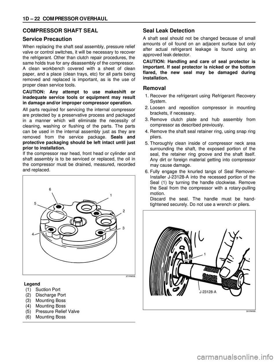
Legend
(1) Suction Port
(2) Discharge Port
(3) Mounting Boss
(4) Mounting Boss
(5) Pressure Relief Valve
(6) Mounting Boss
Seal Leak Detection
A shaft seal should not be changed because of small
amounts of oil found on an adjacent surface but only
after actual refrigerant leakage is found using an
approved leak detector.
CAUTION: Handling and care of seal protector is
important. If seal protector is nicked or the bottom
flared, the new seal may be damaged during
installation.
Removal
1. Recover the refrigerant using Refrigerant Recovery
System.
2. Loosen and reposition compressor in mounting
brackets, if necessary.
3. Remove clutch plate and hub assembly from
compressor as described previously.
4. Remove the shaft seal retainer ring, using snap ring
pliers.
5. Thoroughly clean inside of compressor neck area
surrounding the shaft, the exposed portion of the
seal, the retainer ring groove and the shaft itself.
Any dirt or foreign material getting into compressor
may cause damage.
6. Fully engage the knurled tangs of Seal Remover-
Installer J-23128-A into the recessed portion of the
Seal (1) by turning the handle clockwise. Remove
the Seal from the compressor with a rotary-pulling
motion.
Discard the seal. The handle must be hand-
tightened securely. Do not use a wrench or pliers.
1
2
3
456
871RW006
J-23128-A1
901RW008
Page 280 of 3573
1D Ð 24 COMPRESSOR OVERHAUL
6. Remove any excess oil resulting from installing the
new seal parts from the shaft and inside the
compressor neck.
7. Install the clutch plate and hub assembly as
described previously.8. Reinstall compressor belt and tighten bracket.
9. Evacuate and charge the refrigerant system.
COMPRESSOR PRESSURE RELIEF VALVE
Removal
1. Recover the refrigerant using Refrigerant Recovery
System.
2. Remove old pressure relief valve.
Installation
1. Clean valve seat area on rear head.2. Lubricate O-ring of new pressure relief valve and
O-ring assembly with new 525 viscosity refrigerant
oil. Install new valve and torque in place, 9.0 Nám
(6.1 ft lbs)
3. Evacuate and recharge the system.
4. Leak test system.
COMPRESSOR OIL
Compressor Oil Check
The oil used to lubricate the compressor is circulating
with the refrigerant.
Whenever replacing any component of the system or a
large amount of gas leakage occurs, add oil to maintain
the original amount of oil.
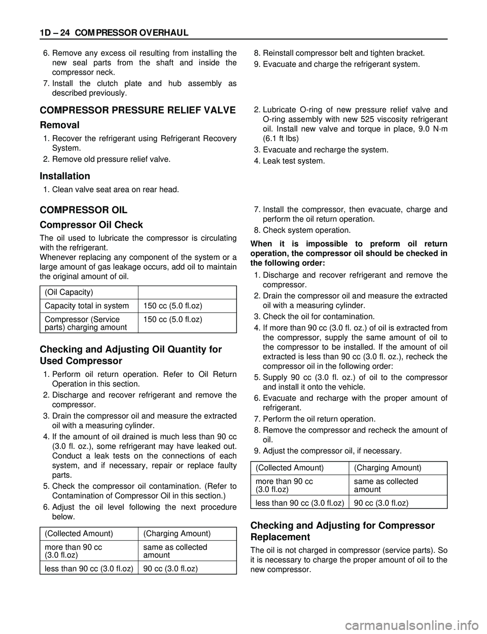
Checking and Adjusting Oil Quantity for
Used Compressor
1. Perform oil return operation. Refer to Oil Return
Operation in this section.
2. Discharge and recover refrigerant and remove the
compressor.
3. Drain the compressor oil and measure the extracted
oil with a measuring cylinder.
4. If the amount of oil drained is much less than 90 cc
(3.0 fl. oz.), some refrigerant may have leaked out.
Conduct a leak tests on the connections of each
system, and if necessary, repair or replace faulty
parts.
5. Check the compressor oil contamination. (Refer to
Contamination of Compressor Oil in this section.)
6. Adjust the oil level following the next procedure
below.7. Install the compressor, then evacuate, charge and
perform the oil return operation.
8. Check system operation.
When it is impossible to preform oil return
operation, the compressor oil should be checked in
the following order:
1. Discharge and recover refrigerant and remove the
compressor.
2. Drain the compressor oil and measure the extracted
oil with a measuring cylinder.
3. Check the oil for contamination.
4. If more than 90 cc (3.0 fl. oz.) of oil is extracted from
the compressor, supply the same amount of oil to
the compressor to be installed. If the amount of oil
extracted is less than 90 cc (3.0 fl. oz.), recheck the
compressor oil in the following order:
5. Supply 90 cc (3.0 fl. oz.) of oil to the compressor
and install it onto the vehicle.
6. Evacuate and recharge with the proper amount of
refrigerant.
7. Perform the oil return operation.
8. Remove the compressor and recheck the amount of
oil.
9. Adjust the compressor oil, if necessary.
Checking and Adjusting for Compressor
Replacement
The oil is not charged in compressor (service parts). So
it is necessary to charge the proper amount of oil to the
new compressor. (Oil Capacity)
Capacity total in system 150 cc (5.0 fl.oz)
Compressor (Service 150 cc (5.0 fl.oz)
parts) charging amount
(Collected Amount) (Charging Amount)
more than 90 cc same as collected
(3.0 fl.oz) amount
less than 90 cc (3.0 fl.oz) 90 cc (3.0 fl.oz)
(Collected Amount) (Charging Amount)
more than 90 cc same as collected
(3.0 fl.oz) amount
less than 90 cc (3.0 fl.oz) 90 cc (3.0 fl.oz)
Page 281 of 3573
COMPRESSOR OVERHAUL 1D Ð 25
1. Perform oil return operation.
2. Discharge and recover the refrigerant and remove
the compressor.
3. Drain the compressor oil and measure the extracted
oil.
4. Check the compressor oil for contamination.
5. Adjust the oil level as required.
6. Evacuate, charge and perform the oil return
operation.
7. Check the system operation.
Contamination of Compressor Oil
Unlike engine oil, no cleaning agent is added to the
compressor oil. Even if the compressor runs for a long
period of time (approximately one season), the oil never
becomes contaminated as long as there is nothing
wrong with the compressor or its method of use.
Inspect the extracted oil for any of the following
conditions:
·The capacity of the oil has increased.
·The oil has changed to red.
·Foreign substances, metal powder, etc., are present
in the oil.
If any of these conditions exists, the compressor
oil is contaminated. Whenever contaminated
compressor oil is discovered, the receiver/drier
must be replaced.
Oil Return Operation
There is close affinity between the oil and the
refrigerant. During normal operation, part of the oil
recirculates with the refrigerant in the system. When
checking the amount of oil in the system, or replacing
any component of the system, the compressor must be
run in advance for oil return operation. The procedure
is as follows:
1. Open all the doors and the engine hood.
2. Start the engine and air conditioning switch to "ON"
and set the fan control knob at its highest position.
3. Run the compressor for more than 20 minutes
between 800 and 1,000 rpm in order to operate the
system.
4. Stop the engine.
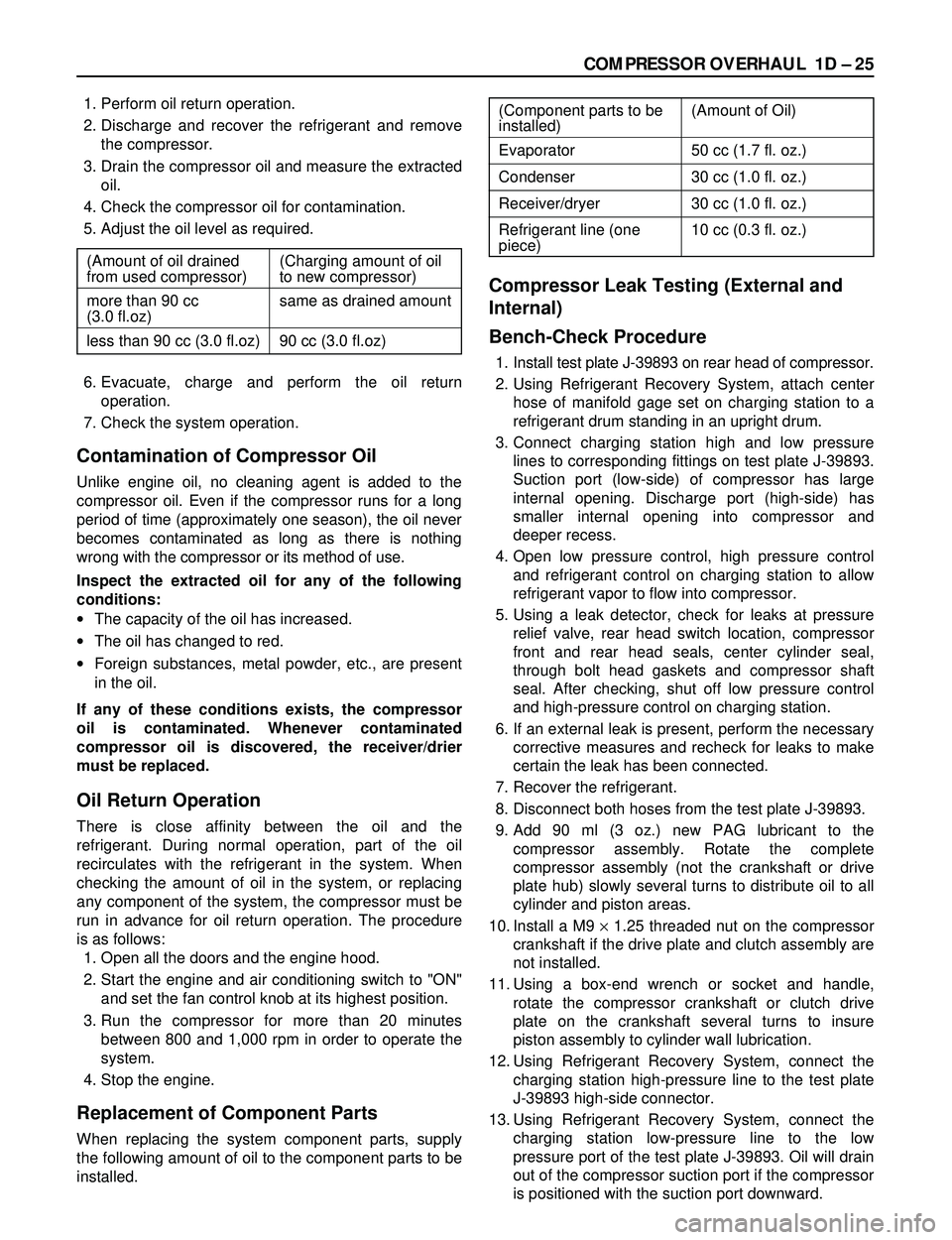
Replacement of Component Parts
When replacing the system component parts, supply
the following amount of oil to the component parts to be
installed.
Compressor Leak Testing (External and
Internal)
Bench-Check Procedure
1. Install test plate J-39893 on rear head of compressor.
2. Using Refrigerant Recovery System, attach center
hose of manifold gage set on charging station to a
refrigerant drum standing in an upright drum.
3. Connect charging station high and low pressure
lines to corresponding fittings on test plate J-39893.
Suction port (low-side) of compressor has large
internal opening. Discharge port (high-side) has
smaller internal opening into compressor and
deeper recess.
4. Open low pressure control, high pressure control
and refrigerant control on charging station to allow
refrigerant vapor to flow into compressor.
5. Using a leak detector, check for leaks at pressure
relief valve, rear head switch location, compressor
front and rear head seals, center cylinder seal,
through bolt head gaskets and compressor shaft
seal. After checking, shut off low pressure control
and high-pressure control on charging station.
6. If an external leak is present, perform the necessary
corrective measures and recheck for leaks to make
certain the leak has been connected.
7. Recover the refrigerant.
8. Disconnect both hoses from the test plate J-39893.
9. Add 90 ml (3 oz.) new PAG lubricant to the
compressor assembly. Rotate the complete
compressor assembly (not the crankshaft or drive
plate hub) slowly several turns to distribute oil to all
cylinder and piston areas.
10. Install a M9 ´1.25 threaded nut on the compressor
crankshaft if the drive plate and clutch assembly are
not installed.
11. Using a box-end wrench or socket and handle,
rotate the compressor crankshaft or clutch drive
plate on the crankshaft several turns to insure
piston assembly to cylinder wall lubrication.
12. Using Refrigerant Recovery System, connect the
charging station high-pressure line to the test plate
J-39893 high-side connector.
13. Using Refrigerant Recovery System, connect the
charging station low-pressure line to the low
pressure port of the test plate J-39893. Oil will drain
out of the compressor suction port if the compressor
is positioned with the suction port downward. (Component parts to be (Amount of Oil)
installed)
Evaporator 50 cc (1.7 fl. oz.)
Condenser 30 cc (1.0 fl. oz.)
Receiver/dryer 30 cc (1.0 fl. oz.)
Refrigerant line (one 10 cc (0.3 fl. oz.)
piece)
(Amount of oil drained (Charging amount of oil
from used compressor) to new compressor)
more than 90 cc same as drained amount
(3.0 fl.oz)
less than 90 cc (3.0 fl.oz) 90 cc (3.0 fl.oz)
Page 325 of 3573
POWER STEERING 2A – 23
DISASSEMBLY
CAUTION:
Do not clamp the steering gear assembly in a vise by the
power cylinder housing.
1. Dust Cover
2. Retaining Ring
3. Back up RIng
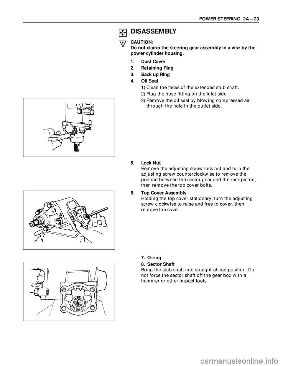
4. Oil Seal
1) Clean the faces of the extended stub shaft.
2) Plug the hose fitting on the inlet side.
3) Remove the oil seal by blowing compressed air
through the hole in the outlet side.
5. Lock Nut
Remove the adjusting screw lock nut and turn the
adjusting screw counterclockwise to remove the
preload between the sector gear and the rack piston,
then remove the top cover bolts.
6. Top Cover Assembly
Holding the top cover stationary, turn the adjusting
screw clockwise to raise and free to cover, then
remove the cover.
7. O-ring
8. Sector Shaft
Bring the stub shaft into straight-ahead position. Do
not force the sector shaft off the gear box with a
hammer or other impact tools.
Page 366 of 3573

2A – 64 SUPPLEMENTAL RESTRAINT SYSTEM STEERING WHEEL & COLUMN
LOCK CYLINDER REPLACEMENT
1
5
4
6
78911
10
3
2
Removal Steps
1. Front console assembly
2. Lower cluster assembly
3. Steering lower cover
4. Inflator module
5. Steering wheel
6. Steering column cover
7. Combination switch and
SRS coil assembly
8. Snap ring
9. Cushion rubber
10. Shift lock cable (for A/T)
11. Lock cylinder assembly
Installation Steps
11. Lock cylinder assembly
10. Shift lock cable (for A/T)
9. Cushion rubber
8. Snap ring
7. Combination switch and
SRS coil assembly
6. Steering column cover
5. Steering wheel
4. Inflator module
3. Steering lower cover
2. Lower cluster assembly
1. Front console assembly
431RT003
These steps are based on the LHD model.
REMOVAL
Preparation:
1) Turn the steering wheel so that the vehicle's wheels
are pointing straight ahead.
2) Turn the ignition switch to "LOCK".
3) Disconnect the battery ground cable, and wait at least
5 minutes.
4) Disconnect the yellow 2way SRS connector located
under the steering column.
Page 368 of 3573

2A – 66 SUPPLEMENTAL RESTRAINT SYSTEM STEERING WHEEL & COLUMN
5. Steering Wheel
Apply a setting mark across the steering wheel and
shaft so parts can be reassembled in their original
position.
Use special tool. Remove the steering wheel.
Move the tires to the straight ahead position before
removing the steering wheel.
Steering wheel remover: 5-8840-0016-0 (J-29752)
CAUTION:
Never apply force to the steering wheel in direction of
the shaft by using a hammer or other impact tools in an
attempt to remove the steering wheel. The steering
shaft is designed as an energy absorbing unit.
6. Steering Column Cover
7. Combination Switch and SRS Coil Assembly
1) Disconnect the wiring harness connectors
located under the steering column.
2) Remove the combination switch assembly with
SRS coil.
NOTE:
The SRS coil is a part of the combination switch
assembly, which can not be replaced separately.
Therefore, be sure not to remove the SRS coil from
the combination switch assembly.
8. Snap Ring
9. Cushion Rubber
10. Shift Lock Cable (for A/T)
11. Lock Cylinder Assembly
Disconnect the starter switch harness connector
located under the steering column.
825RS046
430RS004
Setting mark
Page 373 of 3573
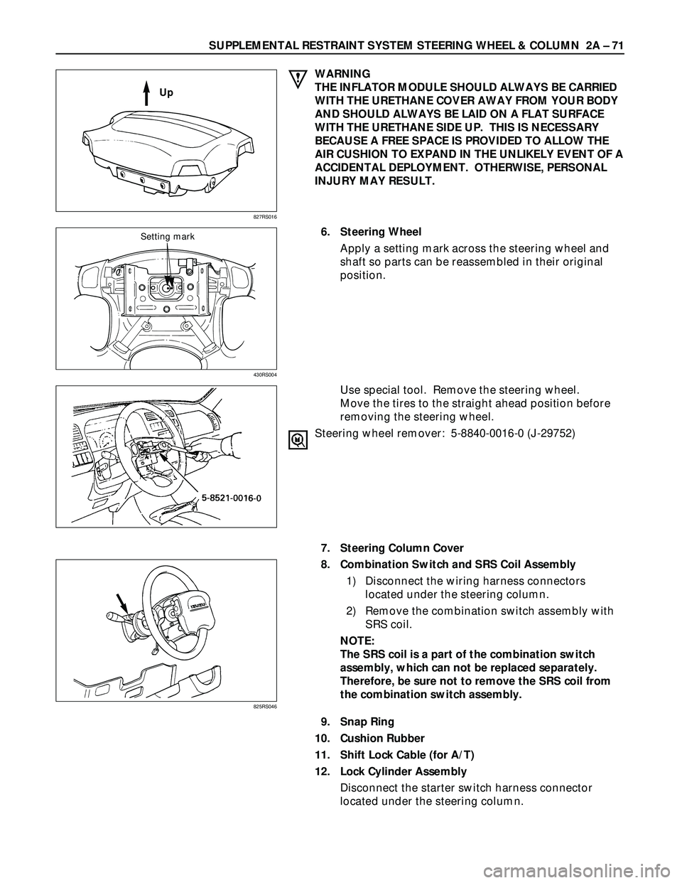
SUPPLEMENTAL RESTRAINT SYSTEM STEERING WHEEL & COLUMN 2A – 71
WARNING
THE INFLATOR MODULE SHOULD ALWAYS BE CARRIED
WITH THE URETHANE COVER AWAY FROM YOUR BODY
AND SHOULD ALWAYS BE LAID ON A FLAT SURFACE
WITH THE URETHANE SIDE UP. THIS IS NECESSARY
BECAUSE A FREE SPACE IS PROVIDED TO ALLOW THE
AIR CUSHION TO EXPAND IN THE UNLIKELY EVENT OF A
ACCIDENTAL DEPLOYMENT. OTHERWISE, PERSONAL
INJURY MAY RESULT.
6. Steering Wheel
Apply a setting mark across the steering wheel and
shaft so parts can be reassembled in their original
position.
Use special tool. Remove the steering wheel.
Move the tires to the straight ahead position before
removing the steering wheel.
Steering wheel remover: 5-8840-0016-0 (J-29752)
7. Steering Column Cover
8. Combination Switch and SRS Coil Assembly
1) Disconnect the wiring harness connectors
located under the steering column.
2) Remove the combination switch assembly with
SRS coil.
NOTE:
The SRS coil is a part of the combination switch
assembly, which can not be replaced separately.
Therefore, be sure not to remove the SRS coil from
the combination switch assembly.
9. Snap Ring
10. Cushion Rubber
11. Shift Lock Cable (for A/T)
12. Lock Cylinder Assembly
Disconnect the starter switch harness connector
located under the steering column.
827RS016
825RS046
Up
430RS004
Setting mark
Page 384 of 3573
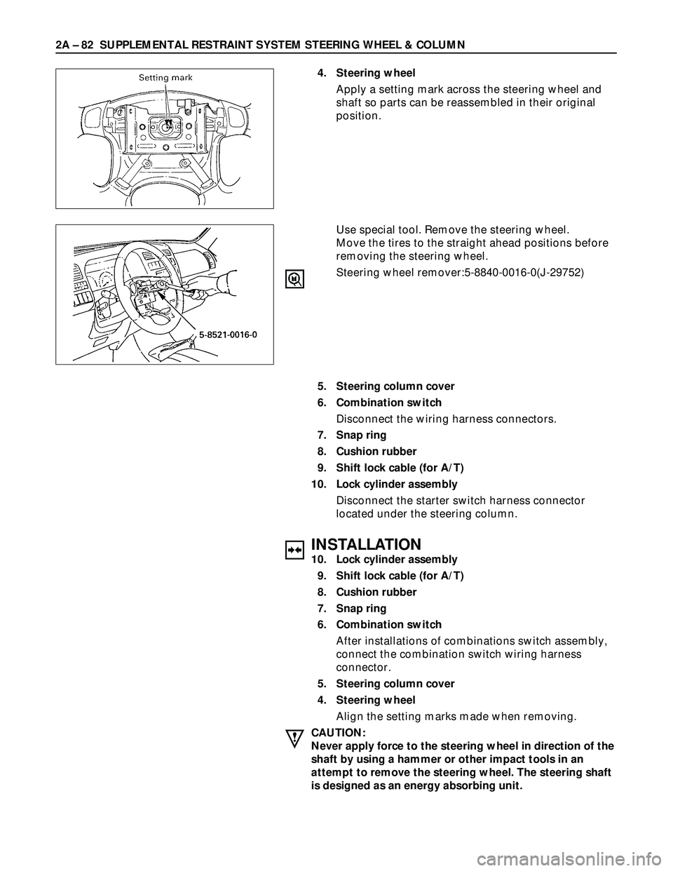
2A – 82 SUPPLEMENTAL RESTRAINT SYSTEM STEERING WHEEL & COLUMN
5. Steering column cover
6. Combination switch
Disconnect the wiring harness connectors.
7. Snap ring
8. Cushion rubber
9. Shift lock cable (for A/T)
10. Lock cylinder assembly
Disconnect the starter switch harness connector
located under the steering column.
INSTALLATION
10. Lock cylinder assembly
9. Shift lock cable (for A/T)
8. Cushion rubber
7. Snap ring
6. Combination switch
After installations of combinations switch assembly,
connect the combination switch wiring harness
connector.
5. Steering column cover
4. Steering wheel
Align the setting marks made when removing.
CAUTION:
Never apply force to the steering wheel in direction of the
shaft by using a hammer or other impact tools in an
attempt to remove the steering wheel. The steering shaft
is designed as an energy absorbing unit.4. Steering wheel
Apply a setting mark across the steering wheel and
shaft so parts can be reassembled in their original
position.
Use special tool. Remove the steering wheel.
Move the tires to the straight ahead positions before
removing the steering wheel.
Steering wheel remover:5-8840-0016-0(J-29752)