Page 766 of 1807
F03330
Battery
B
R/B No.2
ALT
2222AM1 R/B No.2
WR/B No.1
W
2
IG Switch
J/B No.1ABS ECU
IG1
GND1
GND2 ECU IG
444
513 B-Y
1B1J1J 1K A18A20
213*1
*2
A20
A20 A19
A19212
13 25W-B
W-B W-B W-B
IG
IEW-B
*2
NORMAL ABS (2JZ-GE Engine)
SPORT ABS (2JZ-GTE Engine)*1:
*2:
W
- DIAGNOSTICSANTI-LOCK BRAKE SYSTEM
DI-475
703 Author�: Date�:
1997 SUPRA (RM502U)
DTC 41 IG Power Source Circuit
CIRCUIT DESCRIPTION
This is the power source for the ECU, hence the CPU and the actuators.
DTC No.DTC Detecting ConditionTrouble Area
41Voltage at ECU terminal IG1 is less than 9.5 V for more than
10 sec. while vehicle speed is 3 km/h (1.9 mph) or more.�Battery
�IC regulator
�Open or short in power source circuit
Fail safe function:
If trouble occurs in the power source circuit, the ECU cuts off current to the ABS solenoid relay and prohibits
ABS control.
WIRING DIAGRAM
DI4VF-01
Page 768 of 1807
F02629F03334F03335F03336
NORMAL ABS (2JZ-GE Engine):
SPORT ABS (2JZ-GTE Engine):
LOCK
GND
(+)
(-)
(+)
(-)GND
GND
GND
- DIAGNOSTICSANTI-LOCK BRAKE SYSTEM
DI-477
705 Author�: Date�:
1997 SUPRA (RM502U)
3 Check continuity between terminal GND of ABS ECU connector and body
ground.
CHECK:
Measure resistance between terminals GND of ABS ECU con-
nector and body ground.
OK:
Resistance: 1 W or less
NG Repair or replace harness or connector.
OK
Page 770 of 1807

DTC 43, 45 Malfunction is Deceleration Sensor
(SPORT ABS (2JZ-GTE Engine) only)
CIRCUIT DESCRIPTION
DTC No.DTC Dete")
- DIAGNOSTICSANTI-LOCK BRAKE SYSTEM
DI-479
707 Author�: Date�:
1997 SUPRA (RM502U)
DTC 43, 45 Malfunction is Deceleration Sensor
(SPORT ABS (2JZ-GTE Engine) only)
CIRCUIT DESCRIPTION
DTC No.DTC Detecting ConditionTrouble Area
43
Either of the following (1) or (2) is detected:
(1) Input from the deceleration sensor does not change at one
cycle (0 km/h " more than 30km/h " 0 km/h) for 16 times
continuously.
(2) When the brake pedal is not depressed at vehicle speed of
5 km/h or more, forward and backward G (more than 0.4 G) is
detected for 30 seconds or more.
�Deceleration sensor
�Wire harness for deceleration sensor system
45
At vehicle speed of 30 km/h or more, the deceleration sensor
output and vehicle acceleration from wheel speed remain ab-
normally different for 60 seconds or more.�Deceleration sensor
�Wire harness for deceleration sensor system
INSPECTION PROCEDURE
1 Check deceleration sensor (See page DI-442).
NG Replace deceleration sensor.
OK
2 Check for open or short in harness and connector between sensor and ABS ECU
(See page IN-28).
NG Repair or replace harness and connector.
OK
Check and replace ABS ECU.
DI4VG-01
Page 771 of 1807
F03338
Deceleration sensor
3
5
1
2
A23
A23
A23
A23B
W-B
W
R
G
W-B
IG IEA20
A20
A20
A20
3
16
4
17VGS
GL2
GL1
GGNDABS ECU DI-480
- DIAGNOSTICSANTI-LOCK BRAKE SYSTEM
708 Author�: Date�:
1997 SUPRA (RM502U)
DTC 44 Deceleration Sensor Circuit
(SPORT ABS (2JZ-GTE Engine) only)
CIRCUIT DESCRIPTION
This sensor detects deceleration on the vehicle. The sensor signal is used in ABS control. If the sensor func-
tions abnormally, the ABS warning light comes on but the ABS still operates.
DTC No.DTC Detecting ConditionTrouble Area
44
Either of the following (1), (2) or (3) is detected:
(1) IG switch ON and output voltage of GL1 or GL2 remains
0.5 V or less or 4.5 V or more for more than 1.2 sec.
(2) At vehicle speed of 0 km/h, outputs of GL1 and GL2 re-
mains abnormally different for 60 sec. or more
(3) IG switch ON and VGS � 4.4 V, VGS � 5.5 V continues
for 1.2 sec. or more.
�Deceleration sensor
�Open or short in deceleration sensor circuit
WIRING DIAGRAM
DI4VH-01
Page 773 of 1807
F03341
R/B No.2J/B No.1Stop Light
SwitchABS ECU
125
Light
Failure
Sensor
Stop LightJ/B
No.11
10IH
IC
A18 A22 *1*2
G-WG-W
G-W1
2 W STOP
210
1B 1I W-LPOWER
22 W
2
2A
ALTR/B No.2
B
Battery
NORMAL ABS (2JZ-GE Engine)
SPORT ABS (2JS-GTE Engine)
*1:
*2:
1
DI-482
- DIAGNOSTICSANTI-LOCK BRAKE SYSTEM
710 Author�: Date�:
1997 SUPRA (RM502U)
DTC 49 Stop Light Switch Circuit
CIRCUIT DESCRIPTION
This stop light switch senses whether the brake pedal is depressed or released, and sends a signal to the
ECU.
DTC No.DTC Detecting ConditionTrouble Area
491.2 - 1.7 V of STP voltage is continued for 0.3 sec. or more.�Open in stop light circuit
WIRING DIAGRAM
INSPECTION PROCEDURE
1 Check operation of stop light.
CHECK:
Check that stop light lights up when brake pedal is depressed and turns off when brake pedal is released.
NG Replace stop light bulb.
OK
DI4VI-01
Page 774 of 1807
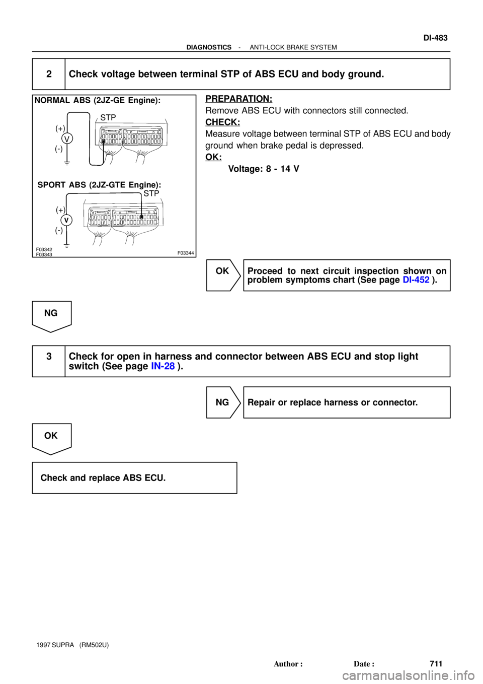
F03342F03343F03344
NORMAL ABS (2JZ-GE Engine):
SPORT ABS (2JZ-GTE Engine):V (+)
(-)
(+)
(-)STP
STP
- DIAGNOSTICSANTI-LOCK BRAKE SYSTEM
DI-483
711 Author�: Date�:
1997 SUPRA (RM502U)
2 Check voltage between terminal STP of ABS ECU and body ground.
PREPARATION:
Remove ABS ECU with connectors still connected.
CHECK:
Measure voltage between terminal STP of ABS ECU and body
ground when brake pedal is depressed.
OK:
Voltage: 8 - 14 V
OK Proceed to next circuit inspection shown on
problem symptoms chart (See page DI-452).
NG
3 Check for open in harness and connector between ABS ECU and stop light
switch (See page IN-28).
NG Repair or replace harness or connector.
OK
Check and replace ABS ECU.
Page 776 of 1807
F03345
R/B No.2ABS ECU*1
*2
W21B22
B
Battery
NORMAL ABS (2JZ-GE Engine)
SPORT ABS (2JZ-GTE Engine)
*1:
*2:
ALTW
R/B No.2
J/B No.12AM1 W1J
442
IG Switch
4 B-Y
J/B No.1
1J1KECU-IG513A18A20 213
212
1325IG 1
GND1
GND2 A20
A20 A19
A19 W-B
W-B W-B
W-B
W-B
*2IE IG
- DIAGNOSTICSANTI-LOCK BRAKE SYSTEM
DI-485
713 Author�: Date�:
1997 SUPRA (RM502U)
DTC Always ON Malfunction in ECU IG Power Source
Circuit
CIRCUIT DESCRIPTION
This is the power source for the ECU, hence the CPU, and the actuators.
DTC No.DTC Detecting ConditionTrouble Area
Always ONVoltage of ECU terminal IG1 remains at more than 17 V for 1
sec. or more.
�Battery
�IC regulator
�Open or short in power source circuit
�ECU
Fail safe function:
If trouble occurs in the power source circuit, the ECU cuts off current to the ABS solenoid relay and prohibits
ABS control.
WIRING DIAGRAM
DI4VK-01
Page 777 of 1807
DI-486
- DIAGNOSTICSANTI-LOCK BRAKE SYSTEM
714 Author�: Date�:
1997 SUPRA (RM502U)
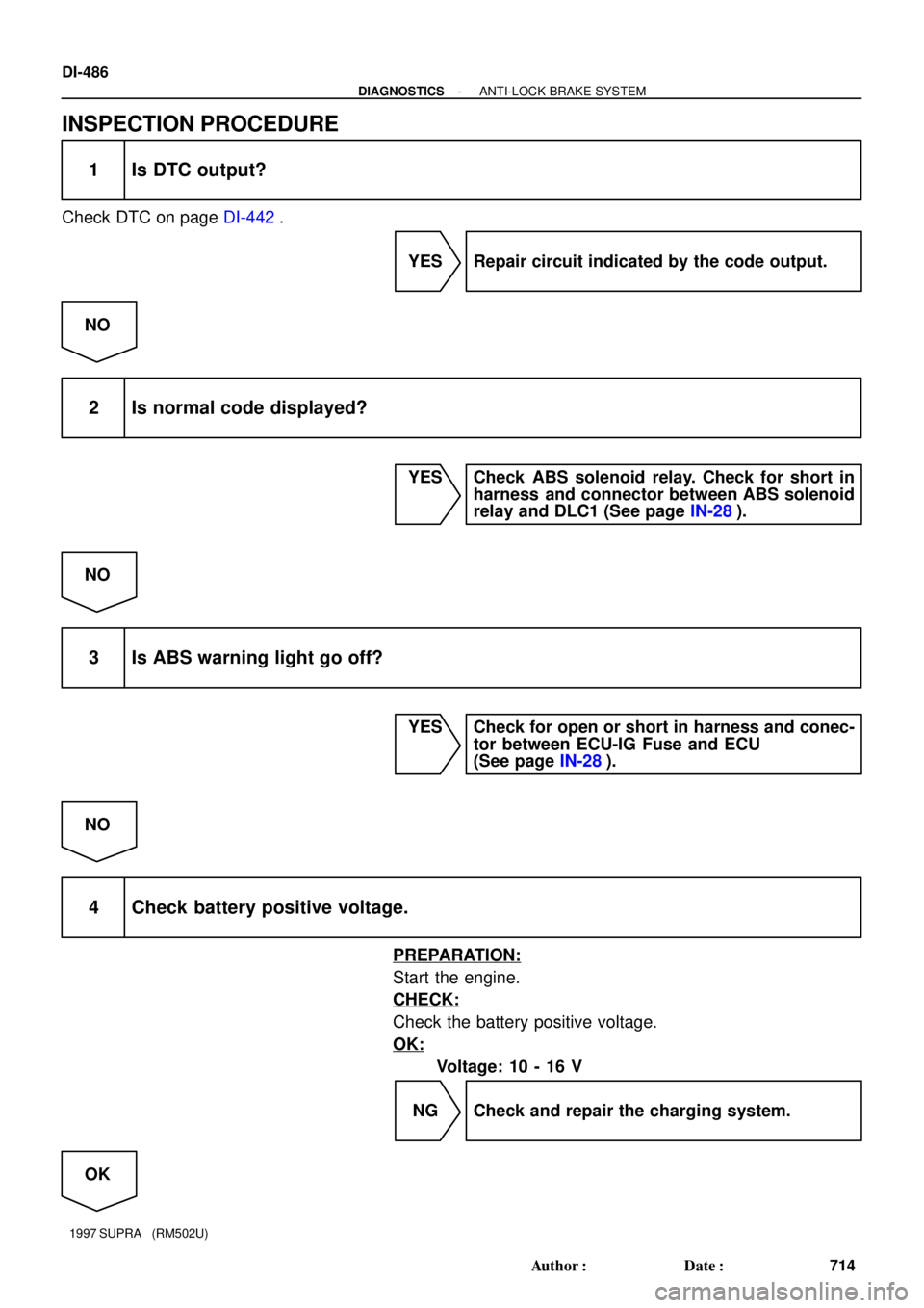
INSPECTION PROCEDURE
1 Is DTC output?
Check DTC on page DI-442.
YES Repair circuit indicated by the code output.
NO
2 Is normal code displayed?
YES Check ABS solenoid relay. Check for short in
harness and connector between ABS solenoid
relay and DLC1 (See page IN-28).
NO
3 Is ABS warning light go off?
YES Check for open or short in harness and conec-
tor between ECU-IG Fuse and ECU
(See page IN-28).
NO
4 Check battery positive voltage.
PREPARATION:
Start the engine.
CHECK:
Check the battery positive voltage.
OK:
Voltage: 10 - 16 V
NG Check and repair the charging system.
OK


SPORT ABS (2JZ-GTE Engine)
*1:
*2:
ALTW
R/B No.2
J/B No.12AM1 W1J
442
IG Switch
4 B-Y
J/B No.1
1J1KECU-IG513A18A20 213
212
1325I")