Page 930 of 1807
I02556
Engine Hood Courtesy
SwitchTheft Deterrent and
Door Lock ECU
W-BGR
DSWH GR1412V
GR
EAIB6 IF3
2
14
9
T13
DI-642
- DIAGNOSTICSTHEFT DETERRENT SYSTEM
870 Author�: Date�:
1997 SUPRA (RM502U)
Engine Hood Courtesy Switch Circuit
CIRCUIT DESCRIPTION
The engine hood courtesy switch is built into the engine hood lock assembly and goes on when the engine
hood is opened and goes off when the engine hood is closed.
WIRING DIAGRAM
DI4XC-01
Page 931 of 1807
I02557
1
2
Disconnect
- DIAGNOSTICSTHEFT DETERRENT SYSTEM
DI-643
871 Author�: Date�:
1997 SUPRA (RM502U)
INSPECTION PROCEDURE
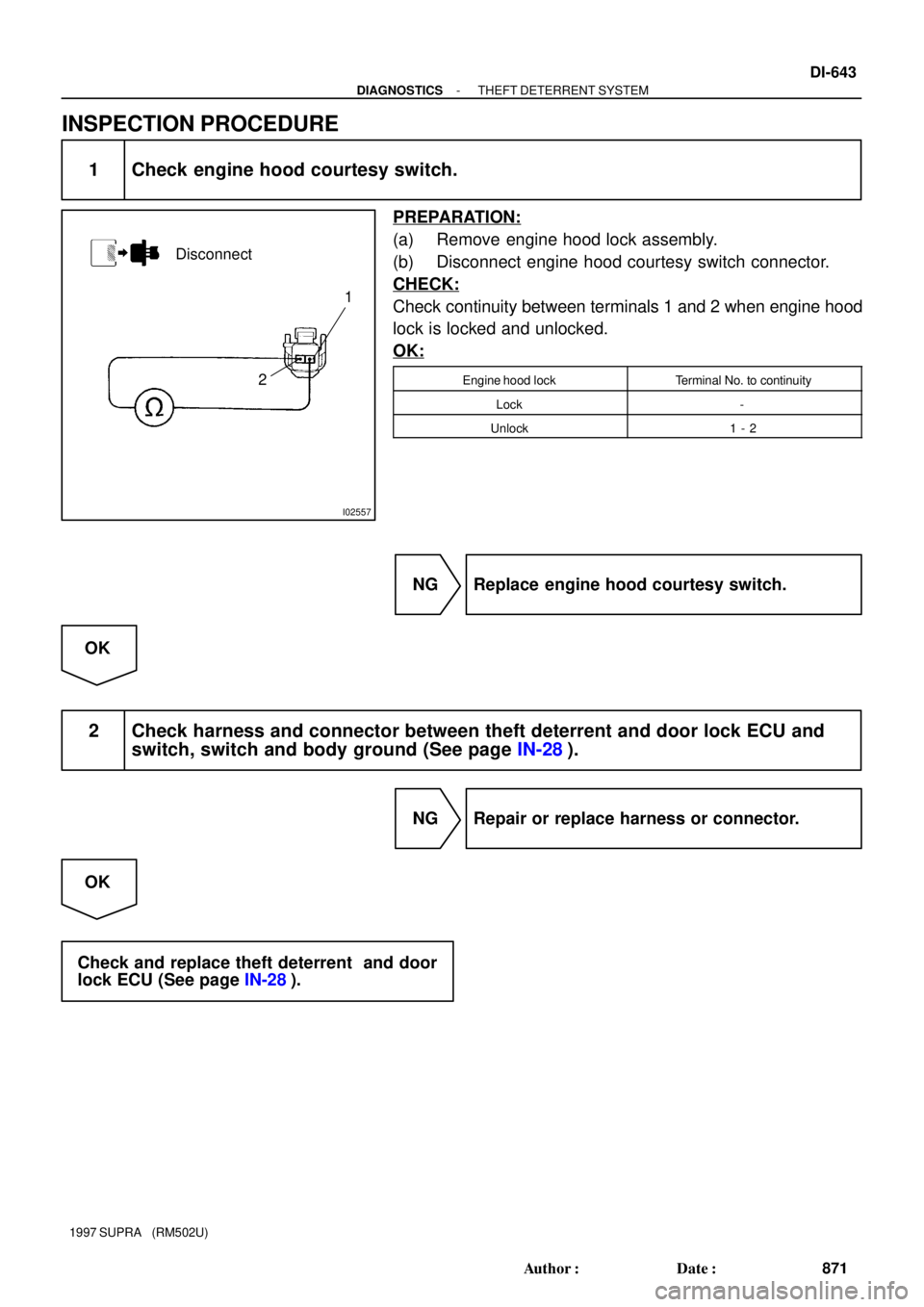
1 Check engine hood courtesy switch.
PREPARATION:
(a) Remove engine hood lock assembly.
(b) Disconnect engine hood courtesy switch connector.
CHECK:
Check continuity between terminals 1 and 2 when engine hood
lock is locked and unlocked.
OK:
Engine hood lockTerminal No. to continuity
Lock-
Unlock1 - 2
NG Replace engine hood courtesy switch.
OK
2 Check harness and connector between theft deterrent and door lock ECU and
switch, switch and body ground (See page IN-28).
NG Repair or replace harness or connector.
OK
Check and replace theft deterrent and door
lock ECU (See page IN-28).
Page 957 of 1807

(2)
(1)
No.
Operation MethodCRUISE MAIN Indicator Light
Blinking PatternDiagnosis
1
3
4
2Turn SET/COAST switch ON
Turn RES/ACC switch ON
Drive at about 40 km/h
(25 mph) or below Turn CANCE")
BE6443
(1)
(2)
(1)
No.
Operation MethodCRUISE MAIN Indicator Light
Blinking PatternDiagnosis
1
3
4
2Turn SET/COAST switch ON
Turn RES/ACC switch ON
Drive at about 40 km/h
(25 mph) or below Turn CANCEL switch ON
Turn stop light switch ON
Depress brake pedal
Turn PNP switch OFF
(Shift to except D position)
Turn clutch switch OFF
(Depress clutch pedal)
Drive at about 40 km/h
(25 mph) or higherSET / COAST switch
circuit is normal
RES / ACC switch circuit
is normal
PNP switch circuit is normal CANCEL switch circuit
is normal
Clutch switch circuit is normal
Vehicle Speed Sensor is
normal
Stop light switch circuit
is normal ON
OFF
0.25 sec.
0.25 sec.
1 sec.Light
ON
OFFLight
ON
OFF Light
ON
OFF Light
ON
OFF Light
ON
OFF Light
Switch OFF
Switch ON
Switch ON
Switch OFF DI-666
- DIAGNOSTICSCRUISE CONTROL SYSTEM
894 Author�: Date�:
1997 SUPRA (RM502U)
5. Using TOYOTA hand-held tester:
INPUT SIGNAL CHECK
HINT:
(1) For check No.1 - No.2
�Turn the ignition switch ON.
(2) For check No.3
�Turn ignition switch ON.
�Shift to D position.
(3) For check No.4
�Jack up the vehicle.
�Start the engine.
�Shift to D position.
(a) Press the control switch to SET/COAST or RES/ACC
position and hold it down or hold it up º1º.
(b) Push the main switch ON º2º.
(c) Check that the CRUISE MAIN indicator light blinks twice
or 3 times repeatedly after 3 seconds.
(d) Turn the SET/COAST or RES/ACC switch OFF.
(e) Operate each switch as listed in the table below.
(f) Read the blinking pattern of the CRUISE MAIN indicator
light.
(g) After performing the check, turn the main switch OFF.
HINT:
When 2 or more signals are input to the ECU, the lowest num-
bered code will be displayed first.
Page 976 of 1807
I02720
IDL164
E9R-B*
1
R*2
R-B*1
2*2T2
IDL
Throttle Position Sensor3
IJ1R-B21
C16
IDL Cruise Control ECU
3*1
R-B*1
R*2R*2
*1: 2JZ-GE Engine
*2: 2JZ-GTE Engine ECM
- DIAGNOSTICSCRUISE CONTROL SYSTEM
DI-685
913 Author�: Date�:
1997 SUPRA (RM502U)
DTC 51 Idle Signal Circuit
CIRCUIT DESCRIPTION
When the idle switch in turned ON, a signal is sent to the ECU. The ECU uses this signal to correct the dis-
crepancy between the throttle valve position and the actuator position sensor value to enable accurate
cruise control at the set speed. If the idle switch is malfunctioning, problem symptoms also occur in the en-
gine, so also inspect the engine.
DTC No.Detection ItemTrouble Area
51Short in idle signal circuit
�Harness or connector between cruise control ECU and
throttle position sensor
�Throttle position sensor
�Cruise control ECU
WIRING DIAGRAM
DI4XW-01
Page 981 of 1807

R-L
(A/T) OD1
S2
*1: 2JZ-GTE Engine
*2: 2JZ-GE Engine R-L
(A/T)R-L
(A/T)
Electronically Controll")
N19614
ECM
E10
E9IJ2
IJ2C16
C16
E2
E2 12
9
8
2229 11
10Cruise Control ECU
OD
ECT BR-B*1LG-B
LG-B*1(A/T)
R-L
(A/T) OD1
S2
*1: 2JZ-GTE Engine
*2: 2JZ-GE Engine R-L
(A/T)R-L
(A/T)
Electronically Controlled Transmission Solenoid*1
*2
S2 DI-690
- DIAGNOSTICSCRUISE CONTROL SYSTEM
918 Author�: Date�:
1997 SUPRA (RM502U)
Electronically Controlled Transmission Communication Circuit
CIRCUIT DESCRIPTION
When driving uphill under cruise control, in order to reduce shifting due to ON-OFF overdrive operation and
to provide smooth driving, when down shifting in the electronically controlled transmission occurs, a signal
to prevent upshift until the end of the uphill slope is sent from the cruise control ECU to the electronically
controlled transmission.
Terminal ECM of the cruise control ECU detects the shift change signal (output to electronically controlled
transmission No.2 solenoid) from the electronically controlled transmission.
If vehicle speed down, also when terminal electronically controlled transmission of the cruise control ECU
receive down shifting signal, it sends a signal from terminal OD to ECM to cut overdrive until the end of the
uphill slope, and the gear shifts are reduced and gear shift points in the electronically controlled transmission
are changed.
WIRING DIAGRAM
DI4XY-01
Page 982 of 1807
I02724
ON
(-)
OD (+)
- DIAGNOSTICSCRUISE CONTROL SYSTEM
DI-691
919 Author�: Date�:
1997 SUPRA (RM502U)
INSPECTION PROCEDURE
1 Check operation of overdrive.
PREPARATION:
Test drive after engine warms up.
CHECK:
Check that overdrive ON e OFF occurs with operation of OD switch ON e OFF.
NG Check and repair electronically controlled
transmission (See page DI-371).
OK
2 Check voltage between terminal OD of harness side connector of cruise control
ECU and body ground.
PREPARATION:
Remove cruise control ECU with connector still connected.
CHECK:
(a) Disconnect cruise control ECU connector.
(b) Turn ignition switch ON.
(c) Measure voltage between terminal OD of harness side
connector of cruise control ECU and body ground.
OK:
Voltage: 10 - 14 V
NG Go to step 5.
OK
Page 983 of 1807
N19837
(-)ECT (+)
DI-692
- DIAGNOSTICSCRUISE CONTROL SYSTEM
920 Author�: Date�:
1997 SUPRA (RM502U)
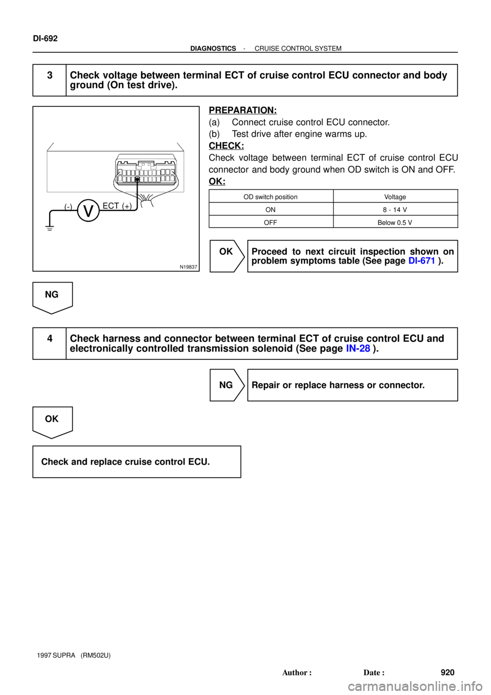
3 Check voltage between terminal ECT of cruise control ECU connector and body
ground (On test drive).
PREPARATION:
(a) Connect cruise control ECU connector.
(b) Test drive after engine warms up.
CHECK:
Check voltage between terminal ECT of cruise control ECU
connector and body ground when OD switch is ON and OFF.
OK:
OD switch positionVoltage
ON8 - 14 V
OFFBelow 0.5 V
OK Proceed to next circuit inspection shown on
problem symptoms table (See page DI-671).
NG
4 Check harness and connector between terminal ECT of cruise control ECU and
electronically controlled transmission solenoid (See page IN-28).
NG Repair or replace harness or connector.
OK
Check and replace cruise control ECU.
Page 985 of 1807
I02725
Ignition Switch5
1JGAUGE
12
1E12
1H J/B No.1
Y
(M/T)1
C15
C152 Cruise Control Clutch Start Switch (M/T)
(M/T)G-R
G-R(A/T)
7IJ2 Y
23
II1
Y
(A/T)4
P2 P29 Park/Neutral Position Switch (A/T)
G-R2
C16
DCruise Control ECU
Y
*1: 2JZ-GTE Engine
*2: 2JZ-GE Engine
DI-694
- DIAGNOSTICSCRUISE CONTROL SYSTEM
922 Author�: Date�:
1997 SUPRA (RM502U)
Park/Neutral Position Switch Circuit
CIRCUIT DESCRIPTION
When the shift position is put in except D position, a signal is sent from the park/neutral position switch to
the ECU. When this signal is input during cruise control driving, the ECU cancels the cruise control.
WIRING DIAGRAM
INSPECTION PROCEDURE
1 Check starter operation.
CHECK:
Check that the starter operates normally and that the engine starts.
NG Proceed to engine troubleshooting
(2JZ-GE: See page DI-24,
2JZ-GTE: See page DI-169).
OK
DI4XZ-01


1
C15
C152 Cruise Control Clutch Start Switch (M/T)
(M/T)G-R
G-R(A/T)
7IJ2 Y
23
II1
Y
(A/T)4
P2 P29 Park/Neutral Position Switch (A/T)
G-R2
C")