Page 988 of 1807

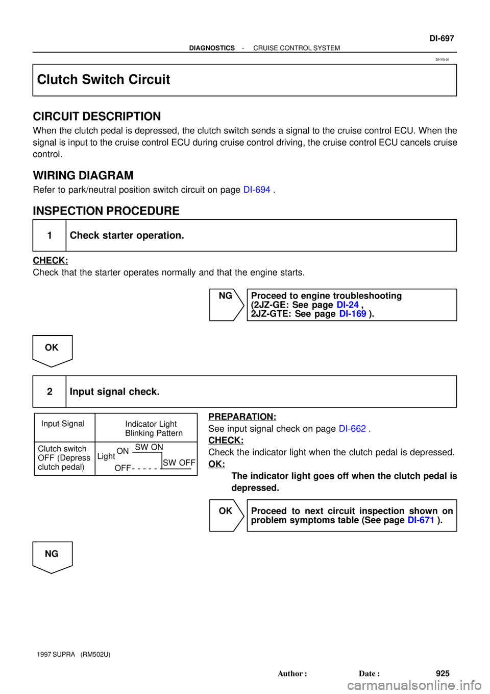
Input Signal
Indicator Light
Blinking Pattern
Clutch switch
OFF (Depress
clutch pedal)
LightON
OFFSW ON
SW OFF
- DIAGNOSTICSCRUISE CONTROL SYSTEM
DI-697
925 Author�: Date�:
1997 SUPRA (RM502U)
Clutch Switch Circuit
CIRCUIT DESCRIPTION
When the clutch pedal is depressed, the clutch switch sends a signal to the cruise control ECU. When the
signal is input to the cruise control ECU during cruise control driving, the cruise control ECU cancels cruise
control.
WIRING DIAGRAM
Refer to park/neutral position switch circuit on page DI-694.
INSPECTION PROCEDURE
1 Check starter operation.
CHECK:
Check that the starter operates normally and that the engine starts.
NG Proceed to engine troubleshooting
(2JZ-GE: See page DI-24,
2JZ-GTE: See page DI-169).
OK
2 Input signal check.
PREPARATION:
See input signal check on page DI-662.
CHECK:
Check the indicator light when the clutch pedal is depressed.
OK:
The indicator light goes off when the clutch pedal is
depressed.
OK Proceed to next circuit inspection shown on
problem symptoms table (See page DI-671).
NG
DI4Y0-01
Page 1004 of 1807

5
B
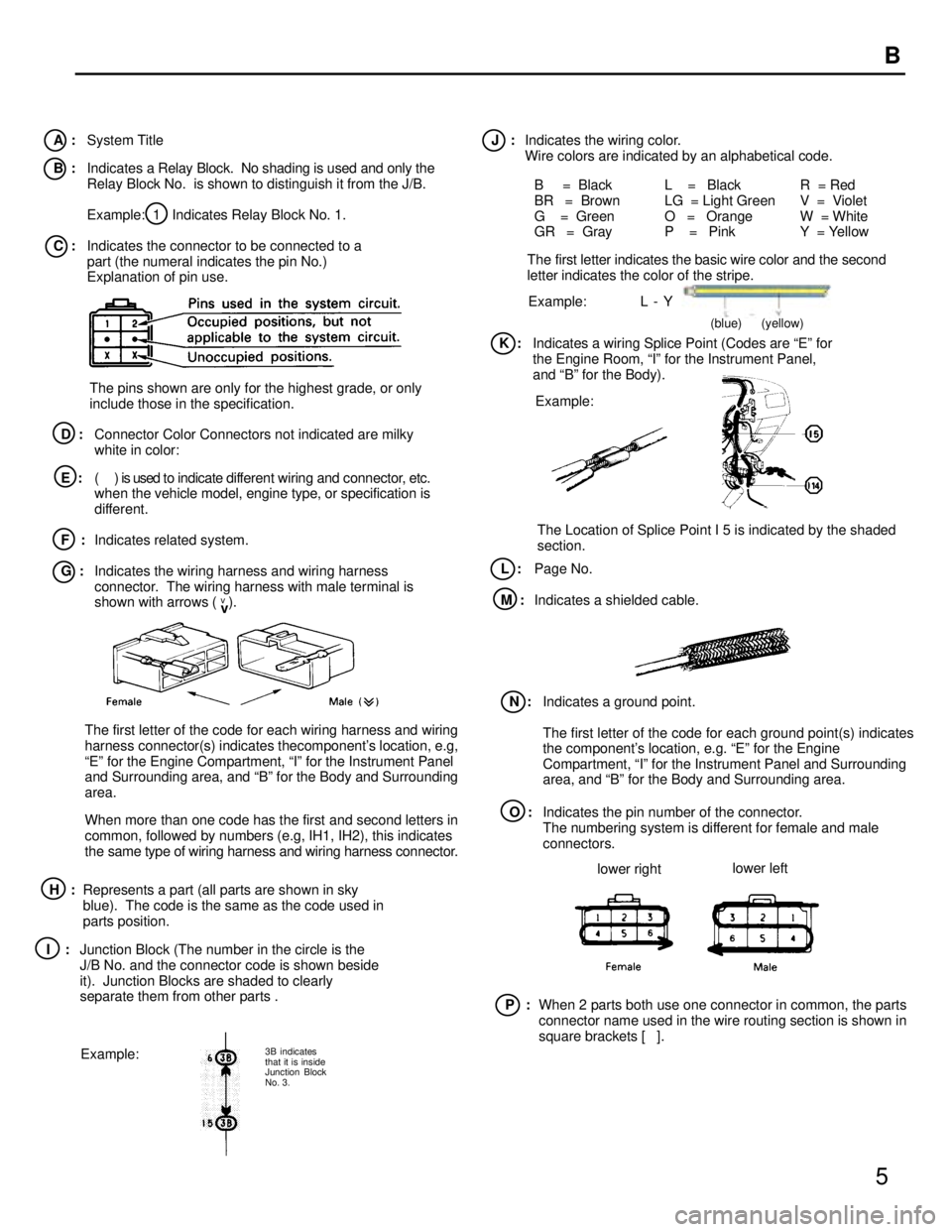
I :Junction Block (The number in the circle is the
J/B No. and the connector code is shown beside
it). Junction Blocks are shaded to clearly
separate them from other parts .
A :System Title
B :Indicates a Relay Block. No shading is used and only the
Relay Block No. is shown to distinguish it from the J/B.
Example: 1 Indicates Relay Block No. 1.
C :Indicates the connector to be connected to a
part (the numeral indicates the pin No.)
Explanation of pin use.J :Indicates the wiring color.
Wire colors are indicated by an alphabetical code.
B = Black
BR = Brown
G = Green
GR = GrayL = Black
LG = Light Green
O = Orange
P = PinkR = Red
V = Violet
W = White
Y = Yellow
The first letter indicates the basic wire color and the second
letter indicates the color of the stripe.
D :Connector Color Connectors not indicated are milky
white in color:
E :( ) is used to indicate different wiring and connector, etc.
when the vehicle model, engine type, or specification is
different.
F :Indicates related system.
G :Indicates the wiring harness and wiring harness
connector. The wiring harness with male terminal is
shown with arrows ( ).
Example: L - Y
K :Indicates a wiring Splice Point (Codes are Eº for
the Engine Room, Iº for the Instrument Panel,
and Bº for the Body).
Example:
The Location of Splice Point I 5 is indicated by the shaded
section.
L :Page No.
M :Indicates a shielded cable.
Example:N :Indicates a ground point.
The first letter of the code for each ground point(s) indicates
the component's location, e.g. Eº for the Engine
Compartment, Iº for the Instrument Panel and Surrounding
area, and Bº for the Body and Surrounding area.
The first letter of the code for each wiring harness and wiring
harness connector(s) indicates thecomponent's location, e.g,
Eº for the Engine Compartment, Iº for the Instrument Panel
and Surrounding area, and Bº for the Body and Surrounding
area.
When more than one code has the first and second letters in
common, followed by numbers (e.g, IH1, IH2), this indicates
the same type of wiring harness and wiring harness connector.
P :When 2 parts both use one connector in common, the parts
connector name used in the wire routing section is shown in
square brackets [ ]. O :Indicates the pin number of the connector.
The numbering system is different for female and male
connectors.
H :Represents a part (all parts are shown in sky
blue). The code is the same as the code used in
parts position.
3B indicates
that it is inside
Junction Block
No. 3. v
v The pins shown are only for the highest grade, or only
include those in the specification.
lower rightlower left
(blue) (yellow)
Page 1014 of 1807
15
C TROUBLESHOOTING
DISCONNECTION AND CONNECTION OF BOLT
TYPE CONNECTORS
For engine control module in this vehicle, connections are used
which require a bolt built into the connector to be screwed down
to securely connect the connector.
1. Disconnect the connector
After completely loosening the bolt, the two parts of the
connector can be separated.
NOTICE:
Do not pull the wire harness when disconnecting the
connector.
2. Connect the connector
NOTICE:
Before connecting the connector, always check that
the terminals are not bent or damaged.
(a) Match the guide section of the male connector
correctly with the female connector, then press
them together.
(b) Tighten the bolt.
Make sure the connectors are completely
connected, by tightening the bolt until there is a
clearance of less than 1 mm (0.04 in.) between the
bottom of male connector and the end of female
connector.
Page 1018 of 1807
19
+
F RELAY LOCATIONS
[Engine Compartment]
[Instrument Panel]
Page 1022 of 1807
23
F RELAY LOCATIONS
2: R/B No. 2Engine Compartment Left (See Page 18): J/B No. 2Engine Compartment Left (See Page 18)
Page 1023 of 1807
24
F
4: R/B No. 4Left Kick Panel (See Page 18)
Rear WIndow Defogger Relay
5: R/B No. 5Engine Compartment Right (See Page 18)
Page 1024 of 1807

Position of Parts in Engine Compartment
E 4 Engine Coolant Temp. Sender
E 5 Engine Coolant Temp. SW
E 6 Engine Hood Courtesy SW
E 7 Engine Oil Level Sensor
F 3 Front Fog Light LH
F 4 Front Fog Light RH
F 5 Front Side Marker Light LH
F 6 Front Side Marker Light RH
F 7 Front Turn Signal Light LH
F 8 Front Turn Signal Light RH and Parking Light RH
F 9 Front Wiper Motor
G 1 Generator
G 2 Generator
H 1 Headlight Hi LH
H 2 Headlight Hi RH
H 3 Headlight Lo LH
H 4 Headlight Lo RH
H 5 Heated Oxygen Sensor (Bank 1 Sensor 1)
H 8 Horn LH
H 9 Horn RH A 1 A/C Ambient Temp Sensor
A 2 A/C Condensor Fan Motor
A 3 A/C Triple Pressure SW
(A/C Dual and Single Pressure SW)
A 4 A/C Magnetic Clutch and Lock Sensor
A 5 A/T Fluid Temp. Sensor
A 6 ABS Actuator
A 7 ABS Actuator
A10 ABS Speed Sensor Front LH
A11 ABS Speed Sensor Front RH
B 1 Back-Up Light SW (M/T)
B 2 Brake Fluid Level Warning SW
C 1 Camshaft Position Sensor No.1
C 2 Camshaft Position Sensor No.2
C 3 Crankshaft Position Sensor
C 4 Cruise Control Actuator
D 1 Data Link Connector 1
D 2 Daytime Running Light Relay No.3
D 3 Daytime Running Light Relay No.3
E 1 EGR Gas Temp. Sensor
E 2 Electronically Controlled Transmission Solenoid
E 3 Engine Coolant Temp. Sensor
[2JZ-GTE]
24
26
G ELECTRICAL WIRING ROUTING
Page 1025 of 1807
![TOYOTA SUPRA 1997 Service Repair Manual Position of Parts in Engine Compartment
[2JZ-GTE]
R 1 Radiator Fan Motor No.1
R 2 Radiator Fan Relay No.1
R 3 Radiator Fan Relay No.2
R20 Radiator Fan Motor No.2
S 1 SFI Resistor
S 2 Starter
S 3 Start TOYOTA SUPRA 1997 Service Repair Manual Position of Parts in Engine Compartment
[2JZ-GTE]
R 1 Radiator Fan Motor No.1
R 2 Radiator Fan Relay No.1
R 3 Radiator Fan Relay No.2
R20 Radiator Fan Motor No.2
S 1 SFI Resistor
S 2 Starter
S 3 Start](/manual-img/14/57469/w960_57469-1024.png)
Position of Parts in Engine Compartment
[2JZ-GTE]
R 1 Radiator Fan Motor No.1
R 2 Radiator Fan Relay No.1
R 3 Radiator Fan Relay No.2
R20 Radiator Fan Motor No.2
S 1 SFI Resistor
S 2 Starter
S 3 Starter
S 5 Sub Throttle Position Sensor
S18 Sub Throttle Valve Motor
T 1 Theft Deterrent Horn
T 2 Throttle Position Sensor
T14 Turbo Pressure Sensor
V 2 VSV (EGR)
V 3 VSV (EVAP)
V 4 VSV (Exhaust Bypass Valve)
V 5 VSV (Exhaust Gas Control Valve)
V 6 VSV (Fuel Pressure Up)
V 7 VSV (Intake Air Control Valve)
V 8 VSV (Waste Gate Valve)
V10 Vehicle Speed Sensor No.1 (Combination Meter)
V11 Vehicle Speed Sensor No.2 (Electronically
Controlled Transmission)
W 1 Washer Motor I 1 Idle AIr Control Valve
I 2 Igniter
I 3 Igniter
I 6 Ignition Coil No.1
I 7 Ignition Coil No.2
I 8 Ignition Coil No.3
I 9 Ignition Coil No.4
I10 Ignition Coil No.5
I11 Ignition Coil No.6
I12 Injector No.1
I13 Injector No.2
I14 Injector No.3
I15 Injector No.4
I16 Injector No.5
I17 Injector No.6
K 1 Knock Sensor (on Front Side)
K 2 Knock Sensor (on Rear Side)
M 1 Mass Air Flow Meter
N 1 Noise Filter
O 1 O/D Direct Clutch Speed Sensor
O 2 Oil Pressure SW
P 1 PPS Solenoid
P 2 Park/Neutral Position SW, Back-Up Light SW and
A/T Indicator Light SW (A/T)
P13 Parking Light LH
25
G