Page 73 of 1807

V08423 Knock Sensor 1
GRECM
KNK
E1 12
E6
WIRING DIAGRAM
DTC P0325Knock Sensor 1 Circuit Malfunction
CIRCUIT DESCRIPTION
Knock sensor is fitted to the cylinder block to detect engine knocking. This sensor contains a piezoelectric element which
generates a voltage when it becomes deformed, which occurs when the cylinder block vibrates due to knocking. If engine
knocking occurs, ignition timing is retarded to suppress it.
DTC No. DTC Detecting Condition Trouble Area
P0325No knock sensor 1 signal to ECM with engine speed,
1,200 rpm or more.� Open or short in knock sensor1 circuit
� Knock sensor 1 (looseness)
� ECM
If the ECM detects the above diagnosis conditions, it operates the fall safe function in which the corrective retard angle
value is set to the maximum value.
� Diagnostic Trouble Code No. and Detection Item
� Circuit Description
The major role and operation, etc. of the circuit
and its component parts are explained.
� Indicates the diagnostic trouble code, diagnostic
trouble code set parameter and suspect area of
the problem.
� Wiring Diagram
This shows a wring diagram of the circuit.
Use the diagram together with ELECTRICAL
WIRING DIAGRAM to thoroughly understand the
circuit.
Wiring colors are indicated by an alphabetical code.
B = Black, L = Blue, R = Red, BR = Brown,
LG = Light Green, V = Violet, G = Green,
O = Orange, W = White, GR = Gray, P = Pink,
Y = Yellow
The first letter indicates the basic wire color and
the second letter indicates the color of the stripe. IN-26
- INTRODUCTIONHOW TO TROUBLESHOOT ECU CONTROLLED
SYSTEMS
26 Author�: Date�:
1997 SUPRA (RM502U)
6. CIRCUIT INSPECTION
How to read and use each page is shown below.
Page 325 of 1807

BR0GB-01
W02787
W02788
W02789
N00759
- BRAKEBRAKE FLUID
BR-5
1805 Author�: Date�:
1997 SUPRA (RM502U)
BRAKE FLUID
BLEEDING
HINT:
If any work is done on the brake system or if air in the brake lines
is suspected, bleed the system of air.
NOTICE:
Do not let brake fluid remain on painted surfaces. Wash it
off immediately.
1. REMOVE RESERVOIR CAP
2. FILL RESERVOIR WITH BRAKE FLUID
Fluid: SAE J1703 or FMVSS No.116DOT3
3. BLEED MASTER CYLINDER
HINT:
If the master cylinder has been disassembled or if the reservoir
becomes empty, bleed the master cylinder.
(a) Disconnect the brake lines from the master cylinder.
(b) Slowly depress the brake pedal and hold it.
(c) Block off the outer holes with your fingers, and release the
brake pedal.
(d) Repeat (b) 3 or 4 times.
4. BLEED BRAKE LINE
(a) Connect the vinyl tube to the brake caliper.
(b) Depress the brake pedal several times, then loosen the
bleeder plug with the pedal held down.
(c) At the point when fluid stops coming out, tighten the
bleeder plug, then release the brake pedal.
(d) Repeat (b) and (c) until all the air in the fluid has been bled
out.
Torque: (Bleeder plug)
11 N´m (110 kgf´cm, 8 ft´lbf)
Page 334 of 1807
R12236
A BR-14
- BRAKEBRAKE MASTER CYLINDER
1814 Author�: Date�:
1997 SUPRA (RM502U)
(c) Place a rag and 2 wooden blocks on the work table and
lightly tap the cylinder flange against the block edges until
the piston drops out of the cylinder.
HINT:
Make sure the distance (A) from the rag to the top of the blocks
is at least 100 mm (3.94 in.).
Page 529 of 1807

CO0ZY-01
Z07402
Drain Plug
Drain Plug CO-2
- COOLINGCOOLANT
1415 Author�: Date�:
1997 SUPRA (RM502U)
REPLACEMENT
1. DRAIN ENGINE COOLANT
(a) Remove the radiator cap.
CAUTION:
To avoid the danger of being burned, do not remove the ra-
diator cap while the engine and radiator are still hot, as fluid
and steam can be blown out under pressure.
(b) Loosen the 2 drain plugs (for the engine and radiator),
and drain the coolant.
HINT:
To prevent the coolant from spraying over the cylinder block,
connect the rubber hose (inside diameter 6 - 8 mm) in the mar-
ket to the union pipe under.
(c) Close the drain plugs.
Torque:
Engine drain plug
29 N´m (300 kgf´cm, 22 ft´lbf)
2. FILL ENGINE COOLANT
(a) Slowly fill the system with coolant.
�Use a good brand of ethylene-glycol base coolant
and mix it according to the manufacturer's direc-
tions.
�Using coolant which includes more than 50 % ethyl-
ene-glycol (but not more than 70 %) is recom-
mended.
NOTICE:
�Do not use an alcohol type coolant.
�The coolant should be mixed with demineralized wa-
ter or distilled water.
Capacity (w/ Heater):
M/TA/T
2JZ-GE7.3 liters
(7.7 US qts, 6.4 lmp. qts)8.3 liters
(8.8 US qts, 7.3 lmp. qts)
2JZ-GTE8.9 liters
(9.4 US qts, 7.8 lmp. qts)8.8 liters
(9.3 US qts, 7.7 lmp. qts)
(b) Install the radiator cap.
(c) Start the engine, and bleed the cooling system.
(d) Refill the reservoir with coolant until it reaches the
ºFULLº line.
3. CHECK ENGINE COOLANT FOR LEAKS
Page 536 of 1807
P25846
Drain Hose
- COOLINGWATER PUMP
CO-9
1422 Author�: Date�:
1997 SUPRA (RM502U)
(f) Remove the 6 bolts, water pump and gasket.
(g) Remove the drain hose.
(h) Remove the O-ring from the cylinder block.
Page 538 of 1807

CO08O-01
P03945
New
O-Ring
P02574
New Gasket
S00913
A
B A
B
AB
BB
- COOLINGWATER PUMP
CO-1 1
1424 Author�: Date�:
1997 SUPRA (RM502U)
INSTALLATION
1. INSTALL WATER PUMP
(a) Install a new O-ring to the cylinder block.
(b) Install the drain hose.
(c) Install a new gasket to the water pump.
(d) Connect the water pump to the water bypass pipe. Do not
install the nut yet.
(e) Install the water pump with the 2 bolts (A) and 4 bolts (B).
Torque: 21 N´m (210 kgf´cm, 15 ft´lbf)
HINT:
Hand tighten the (A) bolts first.
(f) Install the 2 nuts holding the No.2 water bypass pipe to
the water pump.
Torque: 21 N´m (210 kgf´cm, 15 ft´lbf)
(g) 2JZ-GTE:
Connect the No.3 turbo water hose to the water pump.
(h) 2JZ-GE:
Install the connector bracket (for crankshaft position sen-
sor connector) with the bolt.
(i) 2JZ-GE:
Install the engine clamp bracket with the bolt.
(j) Install the generator with the bolt and nut.
Torque: 40 N´m (400 kgf´cm, 30 ft´lbf)
2. 2JZ-GE:
INSTALL NO.1 WATER BYPASS PIPE AND
WATER BYPASS OUTLET
(a) Install 2 new O-rings to the No.1 water bypass pipe.
(b) Install a new O-ring and the water bypass outlet with the
2 bolts.
Torque: 9.0 N´m (90 kgf´cm, 80 in.´lbf)
3. 2JZ-GTE:
INSTALL NO.1 WATER BYPASS PIPE AND
WATER OUTLET
(a) Install 2 new O-rings to the No.1 water bypass pipe.
(b) Apply soapy water to the O-rings.
(c) Install the No.1 water bypass pipe to the water pump.
Page 545 of 1807

Z00570
Radiator Cap Tester
30° or More
Radiator Cap
P11504
CO08U-01
CO-18
- COOLINGRADIATOR
1431 Author�: Date�:
1997 SUPRA (RM502U)
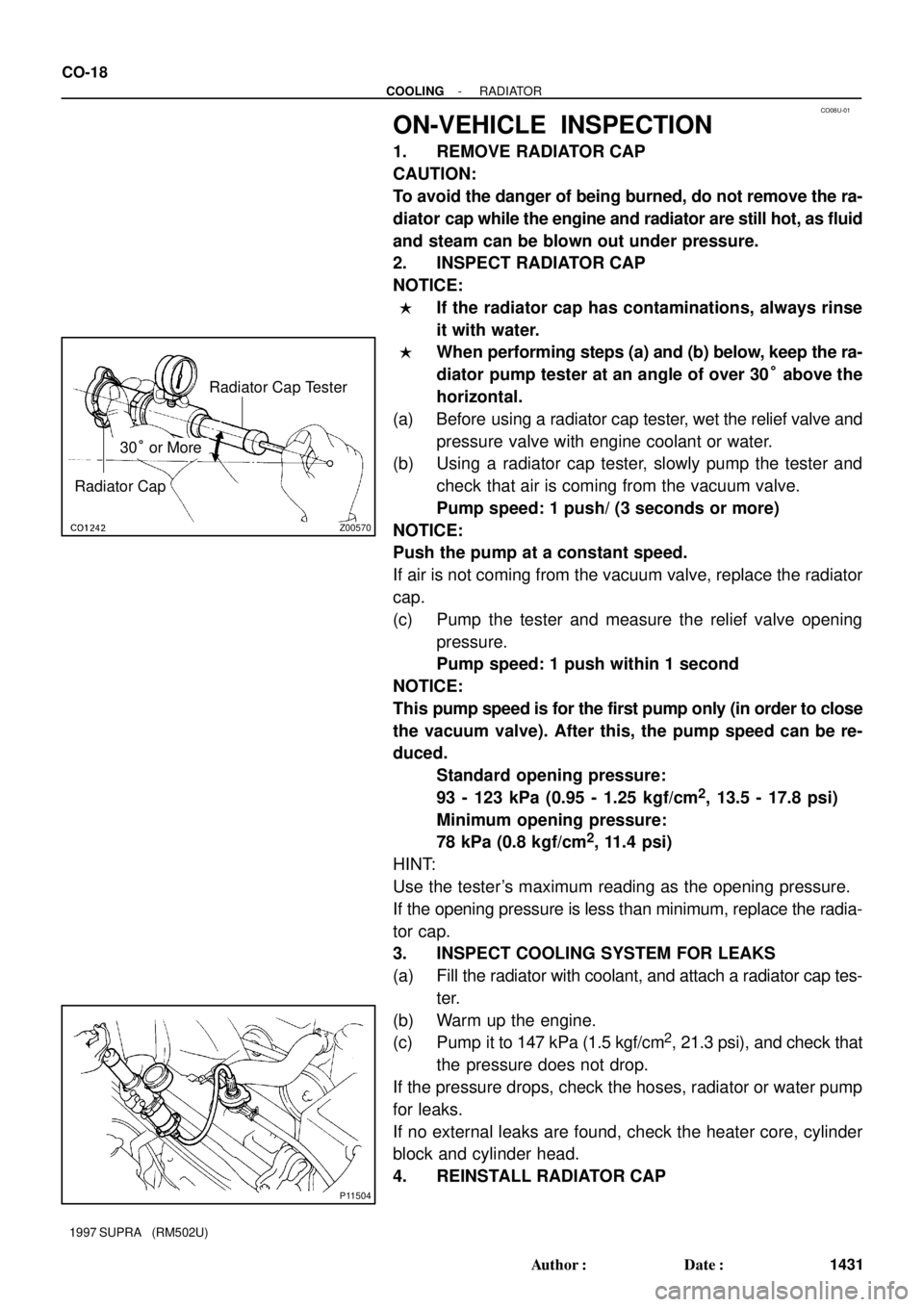
ON-VEHICLE INSPECTION
1. REMOVE RADIATOR CAP
CAUTION:
To avoid the danger of being burned, do not remove the ra-
diator cap while the engine and radiator are still hot, as fluid
and steam can be blown out under pressure.
2. INSPECT RADIATOR CAP
NOTICE:
�If the radiator cap has contaminations, always rinse
it with water.
�When performing steps (a) and (b) below, keep the ra-
diator pump tester at an angle of over 30° above the
horizontal.
(a) Before using a radiator cap tester, wet the relief valve and
pressure valve with engine coolant or water.
(b) Using a radiator cap tester, slowly pump the tester and
check that air is coming from the vacuum valve.
Pump speed: 1 push/ (3 seconds or more)
NOTICE:
Push the pump at a constant speed.
If air is not coming from the vacuum valve, replace the radiator
cap.
(c) Pump the tester and measure the relief valve opening
pressure.
Pump speed: 1 push within 1 second
NOTICE:
This pump speed is for the first pump only (in order to close
the vacuum valve). After this, the pump speed can be re-
duced.
Standard opening pressure:
93 - 123 kPa (0.95 - 1.25 kgf/cm
2, 13.5 - 17.8 psi)
Minimum opening pressure:
78 kPa (0.8 kgf/cm
2, 11.4 psi)
HINT:
Use the tester's maximum reading as the opening pressure.
If the opening pressure is less than minimum, replace the radia-
tor cap.
3. INSPECT COOLING SYSTEM FOR LEAKS
(a) Fill the radiator with coolant, and attach a radiator cap tes-
ter.
(b) Warm up the engine.
(c) Pump it to 147 kPa (1.5 kgf/cm
2, 21.3 psi), and check that
the pressure does not drop.
If the pressure drops, check the hoses, radiator or water pump
for leaks.
If no external leaks are found, check the heater core, cylinder
block and cylinder head.
4. REINSTALL RADIATOR CAP
Page 574 of 1807

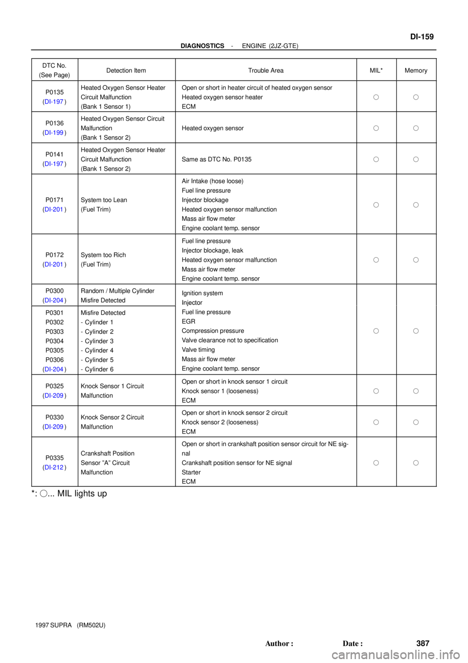
- DIAGNOSTICSENGINE (2JZ-GTE)
DI-159
387 Author�: Date�:
1997 SUPRA (RM502U)DTC No.
(See Page)
Detection ItemTrouble AreaMIL*Memory
P0135
(DI-197)Heated Oxygen Sensor Heater
Circuit Malfunction
(Bank 1 Sensor 1)�Open or short in heater circuit of heated oxygen sensor
�Heated oxygen sensor heater
�ECM
��
P0136
(DI-199)Heated Oxygen Sensor Circuit
Malfunction
(Bank 1 Sensor 2)
�Heated oxygen sensor��
P0141
(DI-197)Heated Oxygen Sensor Heater
Circuit Malfunction
(Bank 1 Sensor 2)
�Same as DTC No. P0135��
P0171
(DI-201)System too Lean
(Fuel Trim)
�Air Intake (hose loose)
�Fuel line pressure
�Injector blockage
�Heated oxygen sensor malfunction
�Mass air flow meter
�Engine coolant temp. sensor
��
P0172
(DI-201)System too Rich
(Fuel Trim)
�Fuel line pressure
�Injector blockage, leak
�Heated oxygen sensor malfunction
�Mass air flow meter
�Engine coolant temp. sensor
��
P0300
(DI-204)Random / Multiple Cylinder
Misfire Detected�Ignition system
�In
jector
P0301
P0302
P0303
P0304
P0305
P0306
(DI-204)Misfire Detected
- Cylinder 1
- Cylinder 2
- Cylinder 3
- Cylinder 4
- Cylinder 5
- Cylinder 6
�Injector
�Fuel line pressure
�EGR
�Compression pressure
�Valve clearance not to specification
�Valve timing
�Mass air flow meter
�Engine coolant temp. sensor
��
P0325
(DI-209)Knock Sensor 1 Circuit
Malfunction�Open or short in knock sensor 1 circuit
�Knock sensor 1 (looseness)
�ECM
��
P0330
(DI-209)Knock Sensor 2 Circuit
Malfunction�Open or short in knock sensor 2 circuit
�Knock sensor 2 (looseness)
�ECM
��
P0335
(DI-212)Crankshaft Position
Sensor ºAº Circuit
Malfunction
�Open or short in crankshaft position sensor circuit for NE sig-
nal
�Crankshaft position sensor for NE signal
�Starter
�ECM
��
*: �... MIL lights up