Page 1297 of 1807
EM0AL-02
P0218510 mm Adhesive Width
2 - 3 mm
Adhesive
Z08040
Protrusion
P12307
(4) (3) (2) (1)
EM0645
Upward
Wide
Narrow
- ENGINE MECHANICAL (2JZ-GTE)CYLINDER HEAD
EM-45
1150 Author�: Date�:
1997 SUPRA (RM502U)
REASSEMBLY
HINT:
�Thoroughly clean all parts to be assembled.
�Before installing the parts, apply fresh engine oil to all slid-
ing and rotating surfaces.
�Replace all gaskets and oil seals with new ones.
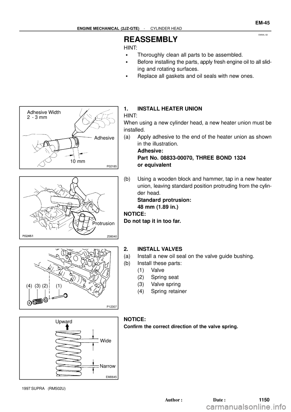
1. INSTALL HEATER UNION
HINT:
When using a new cylinder head, a new heater union must be
installed.
(a) Apply adhesive to the end of the heater union as shown
in the illustration.
Adhesive:
Part No. 08833-00070, THREE BOND 1324
or equivalent
(b) Using a wooden block and hammer, tap in a new heater
union, leaving standard position protruding from the cylin-
der head.
Standard protrusion:
48 mm (1.89 in.)
NOTICE:
Do not tap it in too far.
2. INSTALL VALVES
(a) Install a new oil seal on the valve guide bushing.
(b) Install these parts:
(1) Valve
(2) Spring seat
(3) Valve spring
(4) Spring retainer
NOTICE:
Confirm the correct direction of the valve spring.
Page 1299 of 1807
EM0AM-02
P02111
Z02387
10 mm
Bi-Hexagon
Wrench
12
14 1013
11 84
6125
379
P02424
Painted Mark
Front
P02425
Painted Mark
90°
90°90°
90°
- ENGINE MECHANICAL (2JZ-GTE)CYLINDER HEAD
EM-47
1152 Author�: Date�:
1997 SUPRA (RM502U)
INSTALLATION
1. PLACE CYLINDER HEAD ON CYLINDER BLOCK
(a) Place a new cylinder head gasket in position on the cylin-
der block.
NOTICE:
Be sure to install it correctly.
(b) Place the cylinder head in position on the cylinder head
gasket.
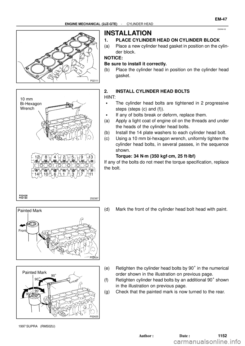
2. INSTALL CYLINDER HEAD BOLTS
HINT:
�The cylinder head bolts are tightened in 2 progressive
steps (steps (c) and (f)).
�If any of bolts break or deform, replace them.
(a) Apply a light coat of engine oil on the threads and under
the heads of the cylinder head bolts.
(b) Install the 14 plate washers to each cylinder head bolt.
(c) Using a 10 mm bi-hexagon wrench, uniformly tighten the
cylinder head bolts, in several passes, in the sequence
shown.
Torque: 34 N´m (350 kgf´cm, 25 ft´lbf)
If any of the bolts do not meet the torque specification, replace
the bolt.
(d) Mark the front of the cylinder head bolt head with paint.
(e) Retighten the cylinder head bolts by 90° in the numerical
order shown in the illustration on previous page.
(f) Retighten cylinder head bolts by an additional 90° shown
in the illustration on previous page.
(g) Check that the painted mark is now turned to the rear.
Page 1311 of 1807
P11919
P11910
Starter
WireDisconnect
P11643
Fuel Inlet Hose
P12534Fuel Return Hose
P11642
(2)
(1)
- ENGINE MECHANICAL (2JZ-GTE)ENGINE UNIT
EM-59
1164 Author�: Date�:
1997 SUPRA (RM502U)
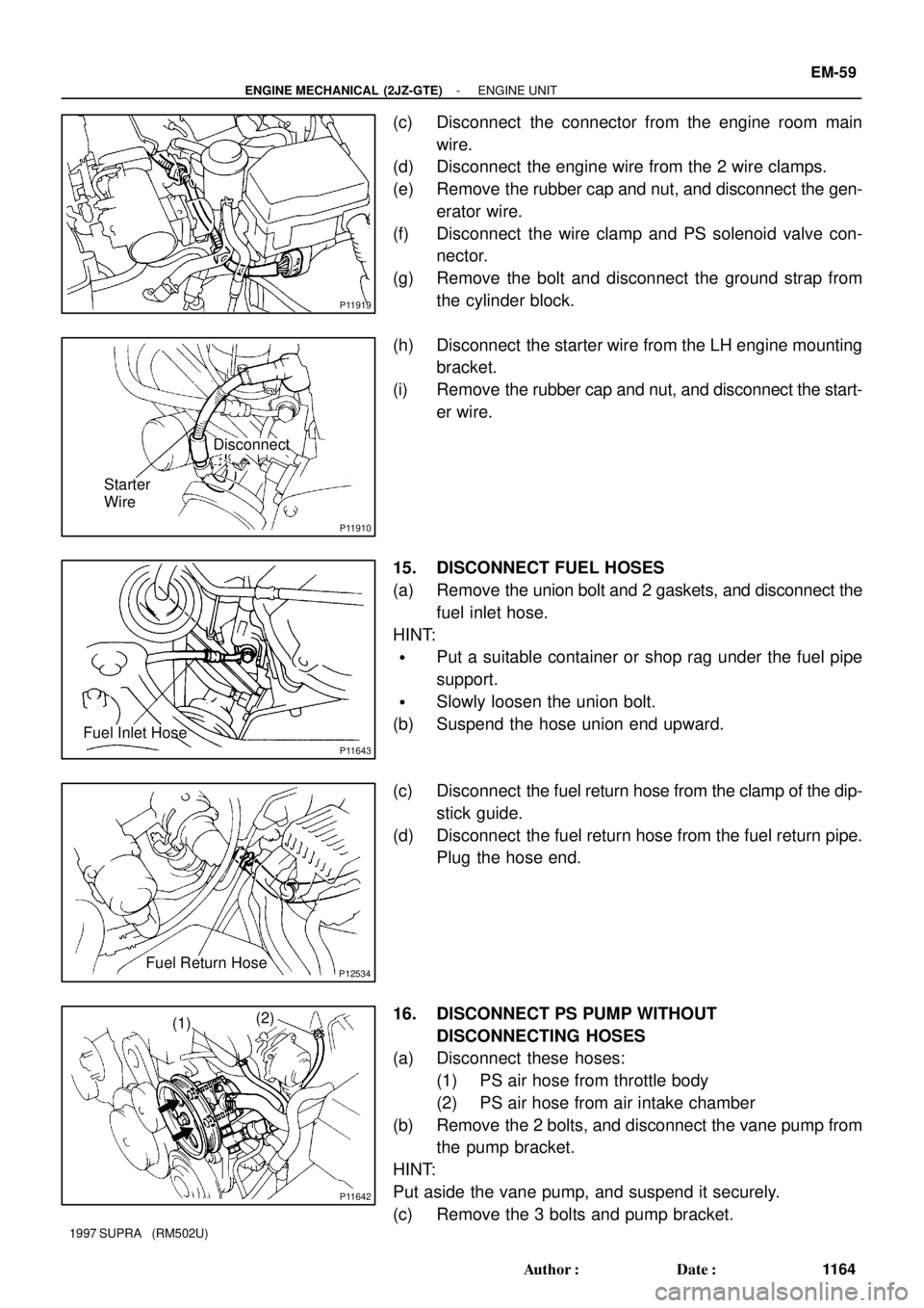
(c) Disconnect the connector from the engine room main
wire.
(d) Disconnect the engine wire from the 2 wire clamps.
(e) Remove the rubber cap and nut, and disconnect the gen-
erator wire.
(f) Disconnect the wire clamp and PS solenoid valve con-
nector.
(g) Remove the bolt and disconnect the ground strap from
the cylinder block.
(h) Disconnect the starter wire from the LH engine mounting
bracket.
(i) Remove the rubber cap and nut, and disconnect the start-
er wire.
15. DISCONNECT FUEL HOSES
(a) Remove the union bolt and 2 gaskets, and disconnect the
fuel inlet hose.
HINT:
�Put a suitable container or shop rag under the fuel pipe
support.
�Slowly loosen the union bolt.
(b) Suspend the hose union end upward.
(c) Disconnect the fuel return hose from the clamp of the dip-
stick guide.
(d) Disconnect the fuel return hose from the fuel return pipe.
Plug the hose end.
16. DISCONNECT PS PUMP WITHOUT
DISCONNECTING HOSES
(a) Disconnect these hoses:
(1) PS air hose from throttle body
(2) PS air hose from air intake chamber
(b) Remove the 2 bolts, and disconnect the vane pump from
the pump bracket.
HINT:
Put aside the vane pump, and suspend it securely.
(c) Remove the 3 bolts and pump bracket.
Page 1317 of 1807
Z16735
A/T
EM0AW-03
Z09545
M/T
A/T
P13200
P13202
Z16756
M/T
Matchmarks
- ENGINE MECHANICAL (2JZ-GTE)ENGINE UNIT
EM-65
1170 Author�: Date�:
1997 SUPRA (RM502U)
INSTALLATION
1. A/T:
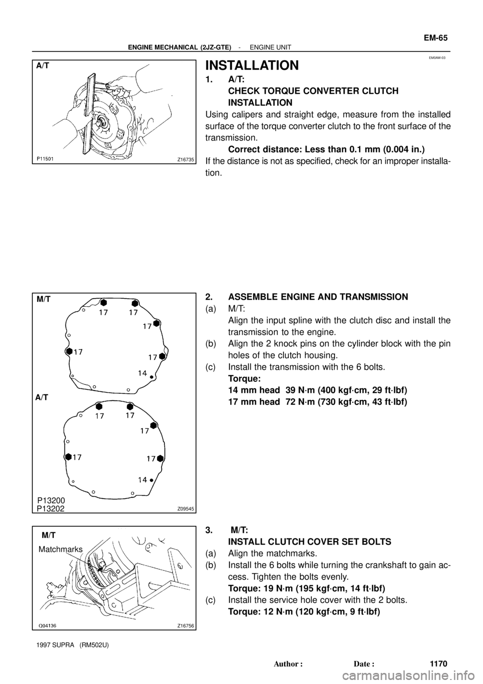
CHECK TORQUE CONVERTER CLUTCH
INSTALLATION
Using calipers and straight edge, measure from the installed
surface of the torque converter clutch to the front surface of the
transmission.
Correct distance: Less than 0.1 mm (0.004 in.)
If the distance is not as specified, check for an improper installa-
tion.
2. ASSEMBLE ENGINE AND TRANSMISSION
(a) M/T:
Align the input spline with the clutch disc and install the
transmission to the engine.
(b) Align the 2 knock pins on the cylinder block with the pin
holes of the clutch housing.
(c) Install the transmission with the 6 bolts.
Torque:
14 mm head 39 N´m (400 kgf´cm, 29 ft´lbf)
17 mm head 72 N´m (730 kgf´cm, 43 ft´lbf)
3. M/T:
INSTALL CLUTCH COVER SET BOLTS
(a) Align the matchmarks.
(b) Install the 6 bolts while turning the crankshaft to gain ac-
cess. Tighten the bolts evenly.
Torque: 19 N´m (195 kgf´cm, 14 ft´lbf)
(c) Install the service hole cover with the 2 bolts.
Torque: 12 N´m (120 kgf´cm, 9 ft´lbf)
Page 1322 of 1807
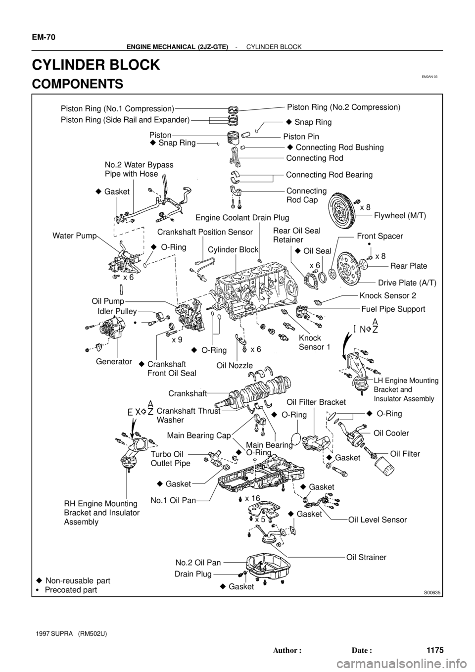
EM0AN-03
S00635
Piston Ring (No.1 Compression)
Piston Ring (Side Rail and Expander)
� Snap RingPiston Ring (No.2 Compression)
� Snap RingPistonPiston Pin
� Connecting Rod Bushing
Connecting Rod
Connecting Rod Bearing
Connecting
Rod Cap
No.2 Water Bypass
Pipe with Hose
� Gasket
x 8
Flywheel (M/T)
Engine Coolant Drain Plug
Rear Oil Seal
Retainer
� Oil Seal
x 6x 8 �
Front Spacer
Rear Plate
Drive Plate (A/T)
Crankshaft Position Sensor
Cylinder Block� O-Ring
Water Pump
x 6
Generator
�
� Crankshaft
Front Oil Sealx 9 Oil Pump
Idler Pulley
� O-RingKnock Sensor 2
Fuel Pipe Supportx 6
Oil Nozzle
Knock
Sensor 1
LH Engine Mounting
Bracket and
Insulator Assembly
Crankshaft
� O-Ring
Oil Cooler
Oil Filter� Gasket � O-Ring
Oil Filter Bracket
� O-RingMain Bearing
Crankshaft Thrust
Washer
Main Bearing Cap
Turbo Oil
Outlet Pipe
� Gasket
No.1 Oil Pan
� Gasket
x 16x 6
x 5
x 14
� GasketRH Engine Mounting
Bracket and Insulator
Assembly
Oil Level Sensor
Oil Strainer
No.2 Oil Pan
Drain Plug
� Non-reusable part
� Precoated part
� Gasket
EM-70
- ENGINE MECHANICAL (2JZ-GTE)CYLINDER BLOCK
1175 Author�: Date�:
1997 SUPRA (RM502U)
CYLINDER BLOCK
COMPONENTS
Page 1323 of 1807
EM0AO-02
P02447
P04467
P12207Knock Sensor
Union for Oil Cooler HoseOil Pressure
Switch
SST
- ENGINE MECHANICAL (2JZ-GTE)CYLINDER BLOCK
EM-71
1176 Author�: Date�:
1997 SUPRA (RM502U)
DISASSEMBLY
1. M/T:
REMOVE FLYWHEEL
2. A/T:
REMOVE DRIVE PLATE
3. INSTALL ENGINE TO ENGINE STAND FOR
DISASSEMBLY
4. REMOVE GENERATOR
5. REMOVE TIMING BELT AND PULLEYS
(See page EM-15)
6. REMOVE CYLINDER HEAD (See page EM-29)
7. REMOVE OIL COOLER (See page LU-20)
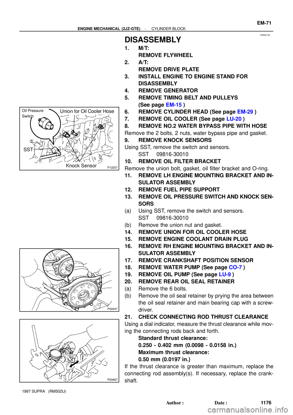
8. REMOVE NO.2 WATER BYPASS PIPE WITH HOSE
Remove the 2 bolts, 2 nuts, water bypass pipe and gasket.
9. REMOVE KNOCK SENSORS
Using SST, remove the switch and sensors.
SST 09816-30010
10. REMOVE OIL FILTER BRACKET
Remove the union bolt, gasket, oil filter bracket and O-ring.
11. REMOVE LH ENGINE MOUNTING BRACKET AND IN-
SULATOR ASSEMBLY
12. REMOVE FUEL PIPE SUPPORT
13. REMOVE OIL PRESSURE SWITCH AND KNOCK SEN-
SORS
(a) Using SST, remove the switch and sensors.
SST 09816-30010
(b) Remove the union nut and gasket.
14. REMOVE UNION FOR OIL COOLER HOSE
15. REMOVE ENGINE COOLANT DRAIN PLUG
16. REMOVE RH ENGINE MOUNTING BRACKET AND IN-
SULATOR ASSEMBLY
17. REMOVE CRANKSHAFT POSITION SENSOR
18. REMOVE WATER PUMP (See page CO-7)
19. REMOVE OIL PUMP (See page LU-9)
20. REMOVE REAR OIL SEAL RETAINER
(a) Remove the 6 bolts.
(b) Remove the oil seal retainer by prying the area between
the oil seal retainer and main bearing cap with a screw-
driver.
21. CHECK CONNECTING ROD THRUST CLEARANCE
Using a dial indicator, measure the thrust clearance while mov-
ing the connecting rods back and forth.
Standard thrust clearance:
0.250 - 0.402 mm (0.0098 - 0.0158 in.)
Maximum thrust clearance:
0.50 mm (0.0197 in.)
If the thrust clearance is greater than maximum, replace the
connecting rod assembly(s). If necessary, replace the crank-
shaft.
Page 1324 of 1807
P02436
P04469
P04599
Plastigage
P02426
EM-72
- ENGINE MECHANICAL (2JZ-GTE)CYLINDER BLOCK
1177 Author�: Date�:
1997 SUPRA (RM502U)
Connecting rod thickness:
25.898 - 25.950 mm (1.0196 - 1.0217 in.)
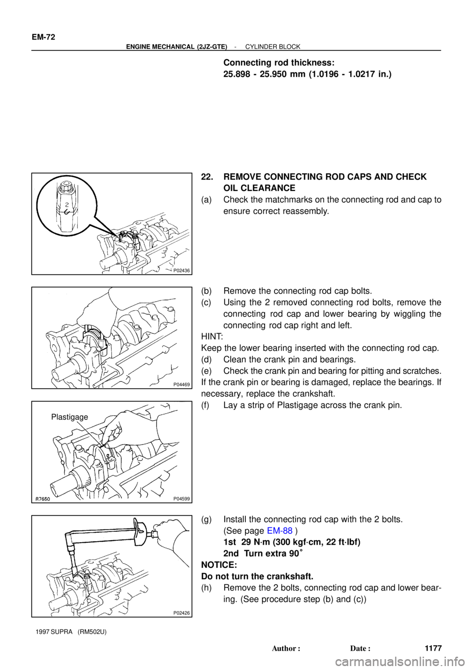
22. REMOVE CONNECTING ROD CAPS AND CHECK
OIL CLEARANCE
(a) Check the matchmarks on the connecting rod and cap to
ensure correct reassembly.
(b) Remove the connecting rod cap bolts.
(c) Using the 2 removed connecting rod bolts, remove the
connecting rod cap and lower bearing by wiggling the
connecting rod cap right and left.
HINT:
Keep the lower bearing inserted with the connecting rod cap.
(d) Clean the crank pin and bearings.
(e) Check the crank pin and bearing for pitting and scratches.
If the crank pin or bearing is damaged, replace the bearings. If
necessary, replace the crankshaft.
(f) Lay a strip of Plastigage across the crank pin.
(g) Install the connecting rod cap with the 2 bolts.
(See page EM-88)
1st 29 N´m (300 kgf´cm, 22 ft´lbf)
2nd Turn extra 90°
NOTICE:
Do not turn the crankshaft.
(h) Remove the 2 bolts, connecting rod cap and lower bear-
ing. (See procedure step (b) and (c))
Page 1325 of 1807
P04470
Z02391
1, 2, 3, 4 or 5Mark
1, 2, or 3 Mark
0, 1 or 2 Mark
No. 1
No. 2
No. 3No. 4No. 6
No. 5
Connecting rod cap
Crankshaft
Use bearingNumber mark
Connecting rod cap º3º +Crankshaft º1º EXAMPLE:
= Total number 4 (Use bearing º4º)0123
12312
01 2
4 2301 2
4 35
- ENGINE MECHANICAL (2JZ-GTE)CYLINDER BLOCK
EM-73
1178 Author�: Date�:
1997 SUPRA (RM502U)
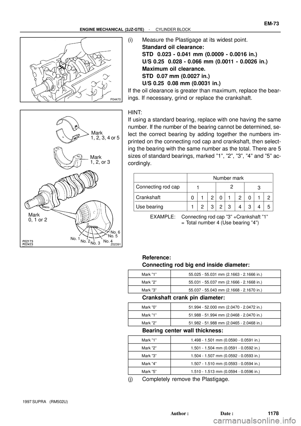
(i) Measure the Plastigage at its widest point.
Standard oil clearance:
STD 0.023 - 0.041 mm (0.0009 - 0.0016 in.)
U/S 0.25 0.028 - 0.066 mm (0.0011 - 0.0026 in.)
Maximum oil clearance.
STD 0.07 mm (0.0027 in.)
U/S 0.25 0.08 mm (0.0031 in.)
If the oil clearance is greater than maximum, replace the bear-
ings. If necessary, grind or replace the crankshaft.
HINT:
If using a standard bearing, replace with one having the same
number. If the number of the bearing cannot be determined, se-
lect the correct bearing by adding together the numbers im-
printed on the connecting rod cap and crankshaft, then select-
ing the bearing with the same number as the total. There are 5
sizes of standard bearings, marked º1º, º2º, º3º, º4º and º5º ac-
cordingly.
Reference:
Connecting rod big end inside diameter:
Mark º1º55.025 - 55.031 mm (2.1663 - 2.1666 in.)
Mark º2º55.031 - 55.037 mm (2.1666 - 2.1668 in.)
Mark º3º55.037 - 55.043 mm (2.1668 - 2.1670 in.)
Crankshaft crank pin diameter:
Mark º0º51.994 - 52.000 mm (2.0470 - 2.0472 in.)
Mark º1º51.988 - 51.994 mm (2.0468 - 2.0470 in.)
Mark º2º51.982 - 51.988 mm (2.0465 - 2.0468 in.)
Bearing center wall thickness:
Mark º1º1.498 - 1.501 mm (0.0590 - 0.0591 in.)
Mark º2º1.501 - 1.504 mm (0.0591 - 0.0592 in.)
Mark º3º1.504 - 1.507 mm (0.0592 - 0.0593 in.)
Mark º4º1.507 - 1.510 mm (0.0593 - 0.0594 in.)
Mark º5º1.510 - 1.513 mm (0.0594 - 0.0596 in.)
(j) Completely remove the Plastigage.