Page 748 of 1807
F02629F02636F02637
LOCK
R/B No.5
(-)
(+)
- DIAGNOSTICSANTI-LOCK BRAKE SYSTEM
DI-457
685 Author�: Date�:
1997 SUPRA (RM502U)
INSPECTION PROCEDURE (2JZ-GTE Engine)
1 Check voltage between terminals 1 and 2 of R/B No.5 (for ABS solenoid relay).
PREPARATION:
Remove ABS solenoid relay from R/B No.5.
CHECK:
Measure voltage between terminals 1 and 2 of R/B No.5 (for
ABS solenoid relay).
OK:
Voltage: 10 - 14 V
NG Check and repair harness or connector.
OK
Page 751 of 1807

DTC 21, 22, 23, 24 ABS Actuator Solenoid Circuit
CIRCUIT DESCRIPTION
This solenoid goes on when signals are receive")
DI-466
- DIAGNOSTICSANTI-LOCK BRAKE SYSTEM
694 Author�: Date�:
1997 SUPRA (RM502U)
DTC 21, 22, 23, 24 ABS Actuator Solenoid Circuit
CIRCUIT DESCRIPTION
This solenoid goes on when signals are received from the ECU and controls the fluid pressure acting on the
brake cylinders, thus controlling the braking force.
DTC No.DTC Detecting ConditionTrouble Area
21
Conditions (1) through (3) continue for 0.05 sec. or more:
(1) ABS solenoid relay terminal (SR) voltage:
Below 1.5V
(2) Voltage of ABS ECU terminal AST:
Battery positive voltage
(3) When power transistor of ECU is ON, voltage of terminal
SFR is 0 V or battery positive voltage.
�ABS actuator
�Open or short in SFR circuit
22
Conditions (1) through (3) continue for 0.05 sec. or more:
(1) ABS solenoid relay terminal (SR) voltage:
Below 1.5V
(2) Voltage of ABS ECU terminal AST:
Battery positive voltage
(3) When power transistor of ECU is ON, voltage of terminal
SFL is 0 V or battery positive voltage.
�ABS actuator
�Open or short in SFL circuit
23
Conditions (1) through (3) continue for 0.05 sec. or more:
(1) ABS solenoid relay terminal (SR) voltage:
Below 1.5V
(2) Voltage of ABS ECU terminal AST:
Battery positive voltage
(3) When power transistor of ECU is ON, voltage of terminal
SRH (SRRH) or SRR (SRRR) is 0 V or battery positive volt-
age.
�ABS actuator
�Open or short in SRH (SRRH) or SRR (SRRR) circuit
24*
Conditions (1) through (3) continue for 0.05 sec. or more:
(1) ABS solenoid relay terminal (SR) voltage:
Below 1.5V
(2) Voltage of ABS ECU terminal AST:
Battery positive voltage
(3) When power transistor of ECU is ON, voltage of terminal
SRLH or SRLR is 0 V or battery positive voltage.
�ABS actuator
�Open or short in SRLH or SRLR circuit
Fail safe function:
If trouble occurs in the ABS actuator solenoid circuit, the ECU cuts off current to the ABS solenoid relay and
prohibits ABS control.
*: SPORT ABS (2JZ-GTE Engine) only
DI4VD-01
Page 752 of 1807
F03320F03321F03322
R/B
No.2
Battery
B
W-B
EA
A6
A7
A6 A9 A9 A8
A19
2A 1
ALT
12
2ABS No.1
2RR1
2
6
DLC1
L-WABS ECU
A19
A19
IB6 Y-GABS ECU
4
R/B
No.2
ABS No.1
1
12 2
BatteryR/B No.2
5
12
4
IB5
A21A20
A6
EA
2JZ-GE Engine (NORMAL ABS):
2
11
ABS ECU 6
IB6
A21
RABS Control Relay
Motor
Relay
A7A7 A7 A7A7
A19
A19
A19
A19
IB5 IB5IB5
IB5 IB5 IB5
ABS Actuator
A9
Solenoid
Relay
5
ABS Pump
Motor
P P-LY Y-R B-Y B-R
Y-GP P-LY Y-R B-Y B-R
5
1
5 6
2
8
7
5 58
7
9 4
31
4 11
10
22
21
16SFLRMonitor
SFLH
SFRR
SFRH
SRR
SRH
AST
5
5
5 35
5
5ABS ECU R 2JZ-GTE Engine (SPORT ABS):
W-B
A64 L-W
ALT
2A
B
ABS ActuatorMonitor
A20
A21
A21
A20
A20
A21
IB5
IB5
IB5
IB5
IB5
IB5
IB5 YY
Y-R Y-R
B-Y
B-Y
B-R
B-R
P
P
P-L
P-L
P-B
P-B
R-L
R-L
Y-GY-G
A7
A7
A7
A7
A7
A7
A7
A7
1DLC1
1
1
5
55
55 22
6
66
44
4 88
33
77
9
1011
12
15
14 ABS Solenoid
Relay
SFRH
SFRR
SFLH
SFLR
SRRH
SRRR
SRLH
SRLR
AST
- DIAGNOSTICSANTI-LOCK BRAKE SYSTEM
DI-467
695 Author�: Date�:
1997 SUPRA (RM502U)
WIRING DIAGRAM
Page 753 of 1807
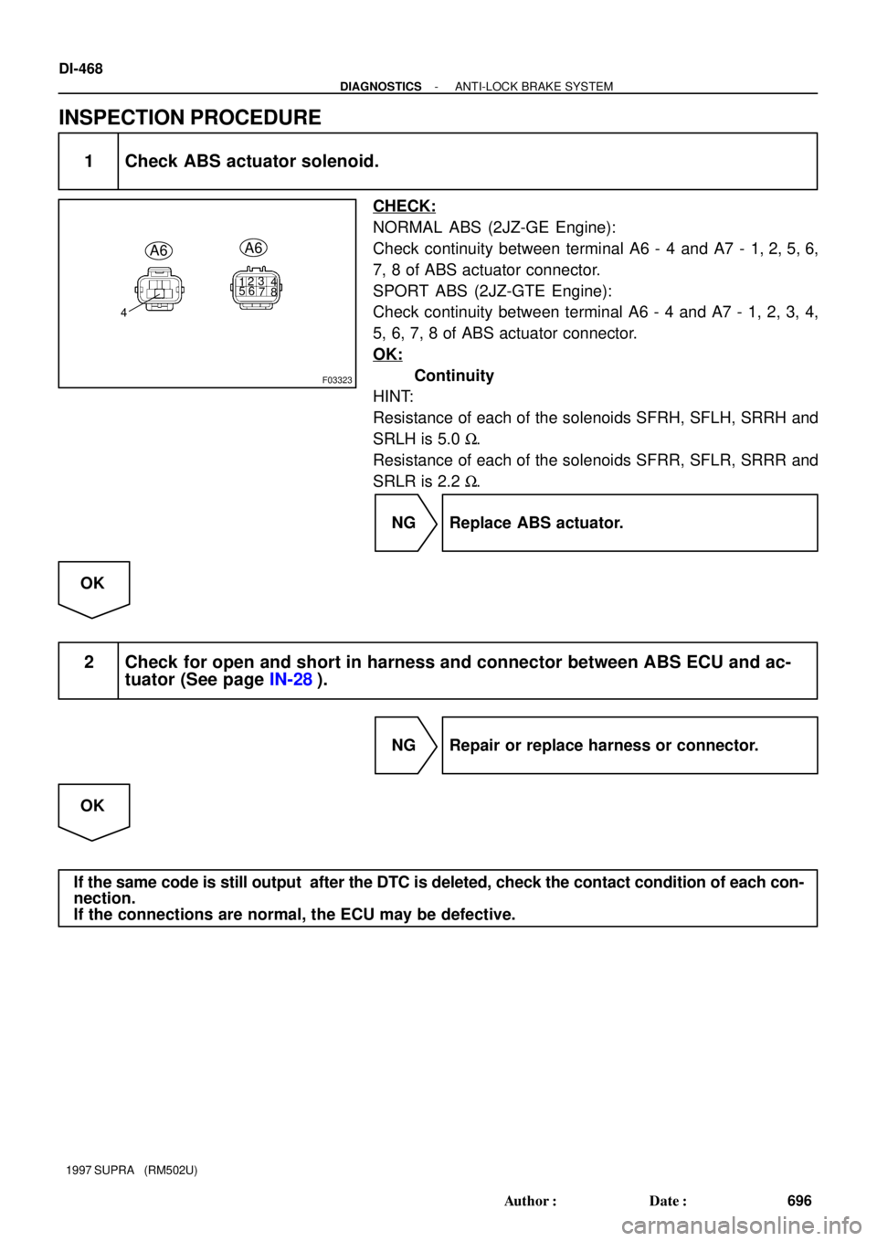
F03323
123
4
56
7
8
4
A6A6
DI-468
- DIAGNOSTICSANTI-LOCK BRAKE SYSTEM
696 Author�: Date�:
1997 SUPRA (RM502U)
INSPECTION PROCEDURE
1 Check ABS actuator solenoid.
CHECK:
NORMAL ABS (2JZ-GE Engine):
Check continuity between terminal A6 - 4 and A7 - 1, 2, 5, 6,
7, 8 of ABS actuator connector.
SPORT ABS (2JZ-GTE Engine):
Check continuity between terminal A6 - 4 and A7 - 1, 2, 3, 4,
5, 6, 7, 8 of ABS actuator connector.
OK:
Continuity
HINT:
Resistance of each of the solenoids SFRH, SFLH, SRRH and
SRLH is 5.0 W.
Resistance of each of the solenoids SFRR, SFLR, SRRR and
SRLR is 2.2 W.
NG Replace ABS actuator.
OK
2 Check for open and short in harness and connector between ABS ECU and ac-
tuator (See page IN-28).
NG Repair or replace harness or connector.
OK
If the same code is still output after the DTC is deleted, check the contact condition of each con-
nection.
If the connections are normal, the ECU may be defective.
Page 755 of 1807
F02626F02643
F02644
R/B
No.2
Battery
B
W-BW-BW-B
EAA6A6 A6
A6
A6 A9 A8 A9 A9A8 A8
A8
A9
IB6
IB6
IB6A19
A19
A19
2A 1
ALT
1 2
2ABS No.1
2RR1
2
6ABS Control Relay
4
3
1 Solenoid
Relay
DLC1 L-BL-B V-W V-WV
V7
8
18ABS ECU
MR
R+
SR
AST
MT 16
9
A19
A19Y-G
G-W 2
13
1
6 5
IB6
IB6 Y-G
G-W 5
3
ABS ActuatorABS ECU 5
4 2
2
L
L-W
Motor
Relay
R/B
No.2
ABS No.1
ALT
1
1
22
Battery
B
R/B No.5
55
5 1
23 4
V-W V-WIB6
IB6 6
2
13
A21
A20
26
A6 A6
ABS Pump MotorEA
MR
R+ 2JZ-GE Engine (NORMAL ABS):
2JZ-GTE Engine (SPORT ABS):
R
5
2
L W-B
A6
131ABS ECU
G-W
G-W 6
IB6
A21
10
MT ABS Motor Relay
V
V R
- DIAGNOSTICSANTI-LOCK BRAKE SYSTEM
DI-461
689 Author�: Date�:
1997 SUPRA (RM502U)
WIRING DIAGRAM
Page 756 of 1807
F02629F02645F02646
LOCK
A8
W02801
ABS Solenoid
Relay
ABS
Actuator
ECUA8
A6A6
A6A6
A193
9
22
2
DI-462
- DIAGNOSTICSANTI-LOCK BRAKE SYSTEM
690 Author�: Date�:
1997 SUPRA (RM502U)
INSPECTION PROCEDURE (2JZ-GE Engine)
1 Check voltage between terminal A8 - 1 of ABS control (motor) relay connector
and body ground.
PREPARATION:
Disconnect the ABS control (motor) relay connector.
CHECK:
Measure voltage between terminal A8 - 1 of ABS control (mo-
tor) relay connector and body ground.
OK:
Voltage: 10 - 14 V
NG Check and repair harness or connector.
OK
2 Check continuity between terminal A8 - 2 of ABS control (motor) relay connector
and terminal A19 - 9 of ABS ECU.
CHECK:
Check continuity between terminal A8 - 2 of ABS control (mo-
tor) relay connector and terminal A19 - 9 of ABS ECU.
OK:
Continuity
HINT:
There is a resistance of 26 ~ 40 W between terminals A6 - 2 and
A6 - 3 of ABS actuator.
NG Repair or replace harness or ABS actuator.
OK
Page 758 of 1807
F02629F02649F02650
LOCK
R/B No.5
(+) (-)
F03315
ABS Solenoid
Relay
ABS
Actuator
ECUA6
A6
A6A6
A21
2
22
3
10
DI-464
- DIAGNOSTICSANTI-LOCK BRAKE SYSTEM
692 Author�: Date�:
1997 SUPRA (RM502U)
INSPECTION PROCEDURE (2JZ-GTE Engine)
1 Check voltage between terminal 1 of R/B No.5 (for ABS motor relay) and body
ground.
PREPARATION:
Remove ABS motor relay from R/B No.5.
CHECK:
Measure voltage between terminal 1 of R/B No.5 (for ABS mo-
tor relay) and body ground.
OK:
Voltage: 10 - 14 V
NG Check and repair harness or connector.
OK
2 Check continuity between terminal 2 of R/B No.5 (for ABS motor relay) and termi-
nal A21 - 10 of ABS ECU.
CHECK:
Check continuity between terminal 2 of R/B No.5 (for ABS mo-
tor relay) and terminal A21 - 10 of ABS ECU.
OK:
Continuity
HINT:
There is a resistance of 26 ~ 40 W between terminals A6 - 2 and
A6 - 3 of ABS actuator.
NG Repair or replace harness or ABS actuator.
OK
Page 761 of 1807
W02989
IB5
IB5
IB2
IB2
IC2
IC2A19 A21
8 Right Front
Speed Sensor2
1L R
EA3
14 9
198
2 20
110
723
322
109FR+
FR-ABS ECU
5V
FL+
FL-
RR+
RR-
RL+
RL- R
L
W
B
V
LG 1
2
4
5
L
P
3 W
B
V
LG 2
2
2 1
1
1 Left Front
Speed Sensor
Right Rear
Speed Sensor
Left Rear
Speed Sensor
*1
3
*2
A19A21
A19
A21
A19
A21
A18
A20
A18
A20
A18
A20
A18
A20 DI-470
- DIAGNOSTICSANTI-LOCK BRAKE SYSTEM
698 Author�: Date�:
1997 SUPRA (RM502U)
WIRING DIAGRAM
*1: NORMAL ABS (2JZ-GE Engine)
*2: SPORT ABS (2JZ-GTE Engine)