Page 917 of 1807
*1
HEAD
(LH-L WR)*2HEAD R/B No.2
FL MAIN
Light Control
Switch
R/B No.2
HEAD
(RH)*1
HEAD
(RH-L WR)*2R-")
I02543
Theft Deterrent and
Door Lock ECU
*1: USA Models
*2: CANADA Models BatteryR/B No.2
HEAD
(LH)*1
HEAD
(LH-L WR)*2HEAD R/B No.2
FL MAIN
Light Control
Switch
R/B No.2
HEAD
(RH)*1
HEAD
(RH-L WR)*2R-Y R-Y R-Y R-Y
R-G R-B
W-B
W-B BRR 2
2
2
22
22
2
11 1 1
4
23
10 16 13
IB2
IF2 2A
EA Headlight Relay
T13
DI-626
- DIAGNOSTICSTHEFT DETERRENT SYSTEM
854 Author�: Date�:
1997 SUPRA (RM502U)
Headlight Control Relay Circuit
CIRCUIT DESCRIPTION
When the theft deterrent system is activated, it causes the Tr in the ECU to switch on and off at approximately
0.2 sec. intervals. This switches the headlight control relay on and off, thus flashing the headlights (See the
wiring diagram below).
In this condition, if any of the following operations is done, the Tr in the ECU goes off and the headlight control
relay switches off, thus stopping the headlights flashing:
(1) The front LH or RH door is unlocked with a key.
(2) The ignition switch is turned to the ACC or ON position.
(3) Approximately 1 minute elapses.
WIRING DIAGRAM
DI4X5-01
Page 918 of 1807
I02544
LOCK
Disconnect
HEAD (+)
- DIAGNOSTICSTHEFT DETERRENT SYSTEM
DI-627
855 Author�: Date�:
1997 SUPRA (RM502U)
INSPECTION PROCEDURE
HINT:
The flow chart below is based on the premise that the headlights light up normally whenever the light control
switch is operated. If headlight operation is not normal when the light control switch is operated, proceed
to troubleshooting on page BE-2.
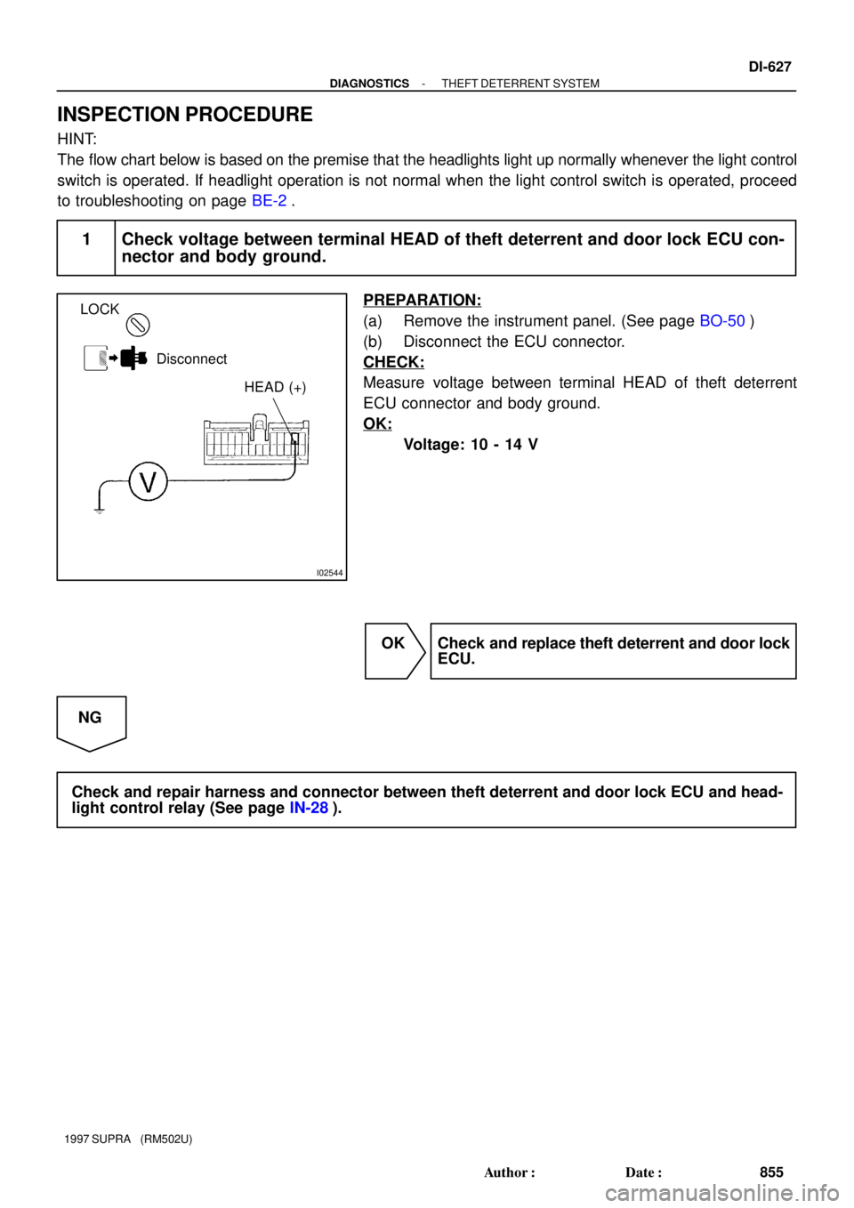
1 Check voltage between terminal HEAD of theft deterrent and door lock ECU con-
nector and body ground.
PREPARATION:
(a) Remove the instrument panel. (See page BO-50)
(b) Disconnect the ECU connector.
CHECK:
Measure voltage between terminal HEAD of theft deterrent
ECU connector and body ground.
OK:
Voltage: 10 - 14 V
OK Check and replace theft deterrent and door lock
ECU.
NG
Check and repair harness and connector between theft deterrent and door lock ECU and head-
light control relay (See page IN-28).
Page 919 of 1807

I02545
I02545
Theft Deterrent and
Door Lock ECUT13
IF2
2 2
2A22 J/B No.1
1B 1K
1C
LG LGG-W G-W
G-WTAIL 11
16
3 5TAIL 1 W-L
W-B
Ta i l
Light
W-B
W-B
1
193
B
Battery
Light
Failure
Sensor
Light Control Switch15
23
G
Taillight Control Relay
B1
BJ
ALT
POWER
W
1
5
5 2 DI-628
- DIAGNOSTICSTHEFT DETERRENT SYSTEM
856 Author�: Date�:
1997 SUPRA (RM502U)
Taillight Control Relay Circuit
CIRCUIT DESCRIPTION
When the theft deterrent system is activated, it causes the Tr in the ECU to switch on and off at approximately
0.2 sec. intervals. This switches the taillight control relay on and off, thus the taillights flash (See the wiring
diagram below).
In this condition, if any of the following operations is done, the Tr in the ECU goes off and the taillight control
relay switches off, thus stopping the taillights flashing:
(1) The front LH or RH door is unlocked with a key.
(2) The ignition switch is turned to the ACC or ON position.
(3) Approximately 1 minute elapses.
WIRING DIAGRAM
DI4X6-01
Page 920 of 1807
I02546
LOCK
Disconnect
TAIL (+)
- DIAGNOSTICSTHEFT DETERRENT SYSTEM
DI-629
857 Author�: Date�:
1997 SUPRA (RM502U)
INSPECTION PROCEDURE
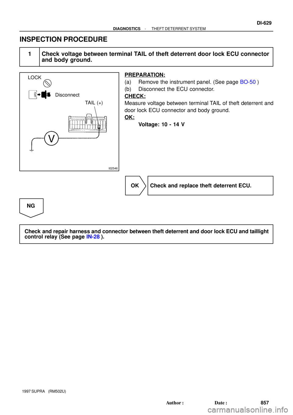
1 Check voltage between terminal TAIL of theft deterrent door lock ECU connector
and body ground.
PREPARATION:
(a) Remove the instrument panel. (See page BO-50)
(b) Disconnect the ECU connector.
CHECK:
Measure voltage between terminal TAIL of theft deterrent and
door lock ECU connector and body ground.
OK:
Voltage: 10 - 14 V
OK Check and replace theft deterrent ECU.
NG
Check and repair harness and connector between theft deterrent and door lock ECU and taillight
control relay (See page IN-28).
Page 921 of 1807
I02547
Theft Deterrent and
Door Lock ECU J/B No.1
Ignition Switch
R/B No.2
R/B No.2
Battery
AM1 ALT
4CIG
WT7
J/B No.1
W 4
4 232 8
58
7 17 1B
1J
2
2
2
12AW
B
ACC L-R
B-R P-L
B-Y
IG1E
1E 1J
1J
ECU-IG DI-630
- DIAGNOSTICSTHEFT DETERRENT SYSTEM
858 Author�: Date�:
1997 SUPRA (RM502U)
Ignition Switch Circuit
CIRCUIT DESCRIPTION
When the ignition switch is turned to the ACC position, battery positive voltage is applied to the terminal ACC
of the ECU. Also, if the ignition switch is turned to the ON position, battery positive voltage is applied to the
terminals ACC and IG of the ECU. When the battery positive voltage is applied to the terminal ACC of the
ECU while the theft deterrent system is activated, the warning stops. Furthermore, power supplied from the
terminals ACC and IG of the ECU is used as power for the door courtesy switch, and position switch, etc.
WIRING DIAGRAM
DI4X7-01
Page 922 of 1807
N08843N14677I04612
ECU-IG
CIG Junciton Block No.1
- DIAGNOSTICSTHEFT DETERRENT SYSTEM
DI-631
859 Author�: Date�:
1997 SUPRA (RM502U)
INSPECTION PROCEDURE
1 Check CIG and ECU-IG fuses.
PREPARATION:
Remove CIG and ECU-IG fuses from J/B No.1.
CHECK:
Check continuity of CIG and ECU-IG fuses.
OK:
Continuity
NG Check for short in all the harness and compo-
nents connected to the CIG and ECU-IG fuses
(See attached wiring diagram).
OK
Page 923 of 1807
I02548
ON
Disconnect
IG (+)ACC (+)
DI-632
- DIAGNOSTICSTHEFT DETERRENT SYSTEM
860 Author�: Date�:
1997 SUPRA (RM502U)
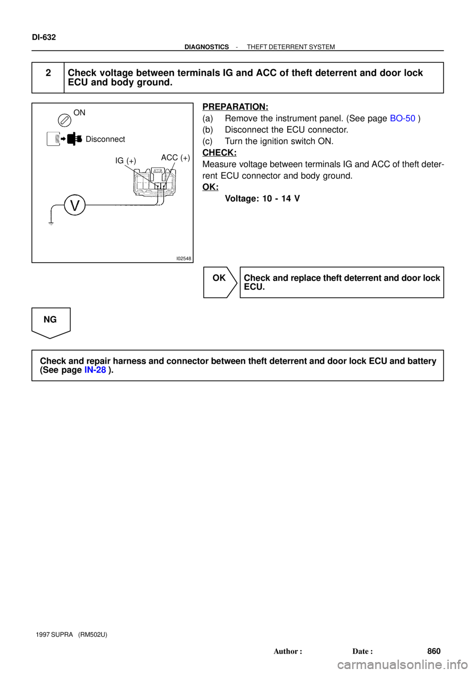
2 Check voltage between terminals IG and ACC of theft deterrent and door lock
ECU and body ground.
PREPARATION:
(a) Remove the instrument panel. (See page BO-50)
(b) Disconnect the ECU connector.
(c) Turn the ignition switch ON.
CHECK:
Measure voltage between terminals IG and ACC of theft deter-
rent ECU connector and body ground.
OK:
Voltage: 10 - 14 V
OK Check and replace theft deterrent and door lock
ECU.
NG
Check and repair harness and connector between theft deterrent and door lock ECU and battery
(See page IN-28).
Page 924 of 1807
I02552
Luggage Compartment Door
Courtesy SwitchTheft Deterrent and
Door Lock ECU
8
LG
IE1DSWL
412V
1T13
LG DI-636
- DIAGNOSTICSTHEFT DETERRENT SYSTEM
864 Author�: Date�:
1997 SUPRA (RM502U)
Luggage Compartment Door Courtesy Switch Circuit
CIRCUIT DESCRIPTION
The luggage compartment door courtesy switch goes on when the back door is opened and goes off when
the back door is closed.
WIRING DIAGRAM
DI4X9-01