Page 949 of 1807
I02567I02567
Theft Deterrent and
Door Lock ECU
Key Unlock Warning
SwitchT13
12V
Y
20 KSW
IF1 Y11
2 1 W-B J/B No.1
W-B
1K
1J12
1
IE
DI-658
- DIAGNOSTICSTHEFT DETERRENT SYSTEM
886 Author�: Date�:
1997 SUPRA (RM502U)
Key Unlock Warning Switch Circuit
CIRCUIT DESCRIPTION
The key unlock warning switch goes on when the ignition key is inserted in the key cylinder and goes off when
the ignition key is removed.
The ECU operates the key confinement prevention function while the key unlock warning switch is on.
WIRING DIAGRAM
DI4XI-01
Page 950 of 1807
I02712
Disconnect
1
2
- DIAGNOSTICSTHEFT DETERRENT SYSTEM
DI-659
887 Author�: Date�:
1997 SUPRA (RM502U)
INSPECTION PROCEDURE
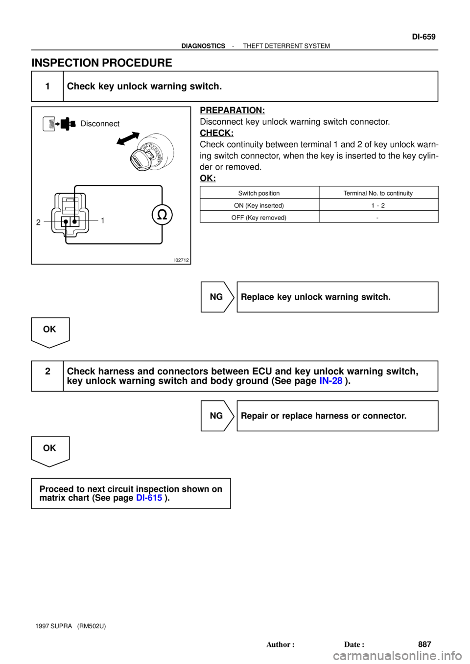
1 Check key unlock warning switch.
PREPARATION:
Disconnect key unlock warning switch connector.
CHECK:
Check continuity between terminal 1 and 2 of key unlock warn-
ing switch connector, when the key is inserted to the key cylin-
der or removed.
OK:
Switch positionTerminal No. to continuity
ON (Key inserted)1 - 2
OFF (Key removed)-
NG Replace key unlock warning switch.
OK
2 Check harness and connectors between ECU and key unlock warning switch,
key unlock warning switch and body ground (See page IN-28).
NG Repair or replace harness or connector.
OK
Proceed to next circuit inspection shown on
matrix chart (See page DI-615).
Page 968 of 1807
N19825
4
3
- DIAGNOSTICSCRUISE CONTROL SYSTEM
DI-677
905 Author�: Date�:
1997 SUPRA (RM502U)
DTC 14 Actuator Mechanical Malfunction
CIRCUIT DESCRIPTION
See page DI-673.
WIRING DIAGRAM
See page DI-673.
INSPECTION PROCEDURE
1 Check actuator arm locking operation.
PREPARATION:
(a) Ignition switch OFF.
(b) Disconnect actuator connector.
CHECK:
(a) Connect the positive � lead from the battery to the termi-
nal 3 of actuator and the negative � lead to terminal 4.
NOTICE:
Do not connect the high tension cables to the wrong bat-
tery terminal. You will damage the cruise control actuator.
(b) Move the control plate by hand.
OK:
Control plate does not move.
NG Replace cruise control actuator.
OK
DI4XS-01
Page 991 of 1807
N08843
J/B No.1
ECU-IG Fuse
I02728
ON
GND (-)
B (+)
DI-700
- DIAGNOSTICSCRUISE CONTROL SYSTEM
928 Author�: Date�:
1997 SUPRA (RM502U)
INSPECTION PROCEDURE
1 Check ECU-IG fuse.
PREPARATION:
Remove ECU-IG fuse from junction block No.1.
CHECK:
Check continuity of ECU-IG fuse.
OK:
Continuity
NG Check for short in all the harness and compo-
nents connected to ECU-IG fuse.
OK
2 Check voltage between terminals B and GND of cruise control ECU connector.
PREPARATION:
Remove cruise control ECU with connector still connected.
CHECK:
(a) Turn ignition switch ON.
(b) Measure voltage between terminals B and GND of cruise
control ECU connector.
OK:
Voltage 10 - 14 V
OK Proceed to next circuit inspection shown on
problem symptoms table (See page DI-671).
NG
Page 994 of 1807
N09001
J/B No.2
DOME Fuse
N19843
(-)
BATT (+)
- DIAGNOSTICSCRUISE CONTROL SYSTEM
DI-703
931 Author�: Date�:
1997 SUPRA (RM502U)
INSPECTION PROCEDURE
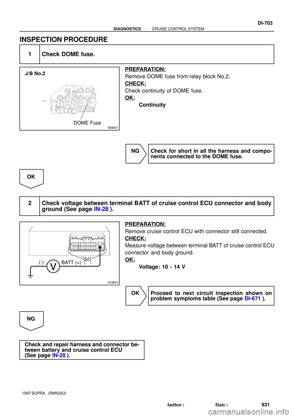
1 Check DOME fuse.
PREPARATION:
Remove DOME fuse from relay block No.2.
CHECK:
Check continuity of DOME fuse.
OK:
Continuity
NG Check for short in all the harness and compo-
nents connected to the DOME fuse.
OK
2 Check voltage between terminal BATT of cruise control ECU connector and body
ground (See page IN-28).
PREPARATION:
Remove cruise control ECU with connector still connected.
CHECK:
Measure voltage between terminal BATT of cruise control ECU
connector and body ground.
OK:
Voltage: 10 - 14 V
OK Proceed to next circuit inspection shown on
problem symptoms table (See page DI-671).
NG
Check and repair harness and connector be-
tween battery and cruise control ECU
(See page IN-28).
Page 1001 of 1807
 EL")
A INTRODUCTION
2
This manual consists of the following 11 sections:
A
B
C
D
E
F
G
H
I
J
K
No.
GROUND POINTS
OVERALL
ELECTRICAL
WIRING DIAGRAM SYSTEM CIRCUITSINDEX
POWER SOURCE
(Current Flow Chart) ELECTRICAL
WIRING ROUTING RELAY LOCATIONS GLOSSARY OF
TERMS AND
SYMBOLS ABBREVIATIONS TROUBLE-
SHOOTING HOW TO USE
THIS MANUAL INTRODUCTION INDEX
Section Description
Index of the contents of this manual.
Brief explanation of each section.
Instructions on how to use this manual.
Describes the basic inspection procedures for electrical circuits.
Defines the abbreviations used in this manual.
Defines the symbols and functions of major parts.
Shows position of the Electronic Control Unit, Relays, Relay Block, etc.
This section is closely related to the system circuit.
Describes position of Parts Connectors, Splice points, Ground points, etc.
This section is closely related to the system circuit.
Describes power distribution from the power supply to various electrical
loads.
Index of the system circuits.
Electrical circuits of each system are shown from the power supply through
ground points. Wiring connections and their positions are shown and
classified by code according to the connection method. (Refer to the
section, How to use this manualº).
The System Outlineº and Service Hintsº useful for troubleshooting are
also contained in this section.
Shows ground positions of all the parts described in this manual.
Provides circuit diagrams showing the circuit connections.
Page 1002 of 1807

3
HOW TO USE THIS MANUAL B
This manual provides information on the electrical circuits installed on vehicles
by dividing them into a circuit for each system.
The actual wiring of each system circuit is shown from the point where the power
source is received from the battery as far as each ground point. (All circuit
diagrams are shown with the switches in the OFF position.)
When troubleshooting any problem, first understand the operation of the circuit
where the problem was detected (see System Circuit section), the power source
supplying power to that circuit (see Power Source section), and the ground
points (see Ground Points section). See the System Outline to understand the
circuit operation.
When the circuit operation is understood, begin troubleshooting of the problem
circuit to isolate the cause. Use Relay Location and Electrical Wiring Routing
sections to find each part, junction block and wiring harness connectors, wiring
harness and wiring harness connectors, splice points, and ground points of each
system circuit. Internal wiring for each junction block is also provided for better
understanding of connection within a junction block.
Wiring related to each system is indicated in each system circuit by arrows
(from
,to ). When overall connections are required, see the Overall Electrical
Wiring Diagram at the end of this manual.
Page 1004 of 1807
. Junction Blocks are shaded to clearly
separate them from other parts .
A :System Tit")
5
B
I :Junction Block (The number in the circle is the
J/B No. and the connector code is shown beside
it). Junction Blocks are shaded to clearly
separate them from other parts .
A :System Title
B :Indicates a Relay Block. No shading is used and only the
Relay Block No. is shown to distinguish it from the J/B.
Example: 1 Indicates Relay Block No. 1.
C :Indicates the connector to be connected to a
part (the numeral indicates the pin No.)
Explanation of pin use.J :Indicates the wiring color.
Wire colors are indicated by an alphabetical code.
B = Black
BR = Brown
G = Green
GR = GrayL = Black
LG = Light Green
O = Orange
P = PinkR = Red
V = Violet
W = White
Y = Yellow
The first letter indicates the basic wire color and the second
letter indicates the color of the stripe.
D :Connector Color Connectors not indicated are milky
white in color:
E :( ) is used to indicate different wiring and connector, etc.
when the vehicle model, engine type, or specification is
different.
F :Indicates related system.
G :Indicates the wiring harness and wiring harness
connector. The wiring harness with male terminal is
shown with arrows ( ).
Example: L - Y
K :Indicates a wiring Splice Point (Codes are Eº for
the Engine Room, Iº for the Instrument Panel,
and Bº for the Body).
Example:
The Location of Splice Point I 5 is indicated by the shaded
section.
L :Page No.
M :Indicates a shielded cable.
Example:N :Indicates a ground point.
The first letter of the code for each ground point(s) indicates
the component's location, e.g. Eº for the Engine
Compartment, Iº for the Instrument Panel and Surrounding
area, and Bº for the Body and Surrounding area.
The first letter of the code for each wiring harness and wiring
harness connector(s) indicates thecomponent's location, e.g,
Eº for the Engine Compartment, Iº for the Instrument Panel
and Surrounding area, and Bº for the Body and Surrounding
area.
When more than one code has the first and second letters in
common, followed by numbers (e.g, IH1, IH2), this indicates
the same type of wiring harness and wiring harness connector.
P :When 2 parts both use one connector in common, the parts
connector name used in the wire routing section is shown in
square brackets [ ]. O :Indicates the pin number of the connector.
The numbering system is different for female and male
connectors.
H :Represents a part (all parts are shown in sky
blue). The code is the same as the code used in
parts position.
3B indicates
that it is inside
Junction Block
No. 3. v
v The pins shown are only for the highest grade, or only
include those in the specification.
lower rightlower left
(blue) (yellow)