Page 933 of 1807
 ON
Connect
I02551
Disconnect
1 2
DI-634
- DIAGNOSTICSTHEFT DETERRENT SYSTEM
862 Author�: Date�:
1997 SUPRA (RM502U)
INSPECTION PROCEDURE
1 Check voltage between terminal 1 of luggage co")
I02550
1 (+) ON
Connect
I02551
Disconnect
1 2
DI-634
- DIAGNOSTICSTHEFT DETERRENT SYSTEM
862 Author�: Date�:
1997 SUPRA (RM502U)
INSPECTION PROCEDURE
1 Check voltage between terminal 1 of luggage compartment door key lock and
unlock switch connector and body ground.
PREPARATION:
(a) Remove deck trim rear cover.
(b) Turn the ignition switch ON.
CHECK:
Measure voltage between terminal 1 of luggage compartment
door key lock and unlock switch connector and body ground,
when the key is turned to the unlock side and not turned.
OK:
Key operationVoltage
Turned to the unlock side0 V
Not turnedBattery positive voltage
OK Check and replace theft deterrent and door lock
ECU. *1
NG
2 Check luggage compartment door key lock and unlock switch.
PREPARATION:
Disconnect luggage compartment door key lock and unlock
switch connector.
CHECK:
Check continuity between terminals 1 and 2, when the key is
turned to the unlock side and not turned.
OK:
Key positionTerminal No. to continuity
Turned to unlock side1 - 2
Not turned-
NG Repair or replace luggage compartment door
key lock and unlock switch.
OK
Page 934 of 1807
- DIAGNOSTICSTHEFT DETERRENT SYSTEM
DI-635
863 Author�: Date�:
1997 SUPRA (RM502U)
3 Check harness and connector between theft deterrent and door lock ECU and
key unlock switch, key unlock switch and body ground (See page IN-28).
NG Repair or replace harness or connector.
OK
Check and replace theft deterrent and door
lock ECU.
*
1: When there is a malfunction that the theft deterrent system cannot be set, proceed to the next numbered
circuit inspection shown on matrix chart (See page DI-615).
Page 935 of 1807
I02558I02558
Theft Deterrent and
Door Lock ECU
BatteryR/B No.2
J/B No.1
DOME
R +B1
W-B E
41 R 5 1
2
B2A
1B1E11
IH
T13
T7
DI-644
- DIAGNOSTICSTHEFT DETERRENT SYSTEM
872 Author�: Date�:
1997 SUPRA (RM502U)
ECU Power Source-Circuit
CIRCUIT DESCRIPTION
This circuit provides power to operate the theft deterrent and door lock ECU.
WIRING DIAGRAM
DI4XD-01
Page 936 of 1807
N09001
Relay Block No.2
DOME Fuse
- DIAGNOSTICSTHEFT DETERRENT SYSTEM
DI-645
873 Author�: Date�:
1997 SUPRA (RM502U)
INSPECTION PROCEDURE
1 Check DOME fuse.
PREPARATION:
Remove DOME fuse from R/B No.2.
CHECK:
Check continuity of DOME fuse.
OK:
Continuity
NG Check for short in all the harness and compo-
nents connected to the DOME fuse
(See attached wiring diagram).
OK
Page 937 of 1807
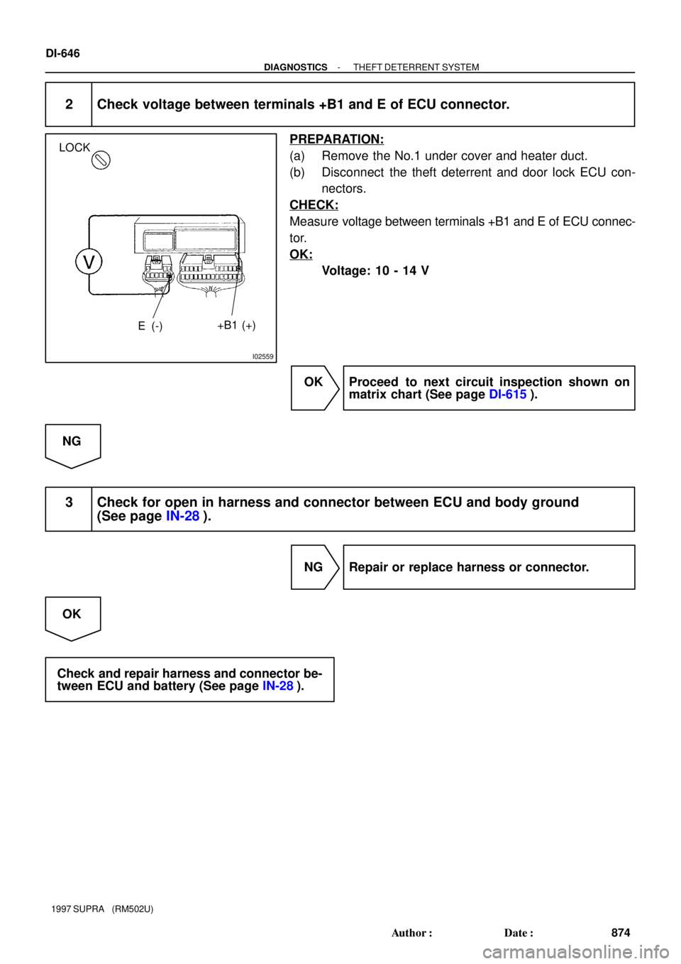
I02559
LOCK
E (-)+B1 (+)
DI-646
- DIAGNOSTICSTHEFT DETERRENT SYSTEM
874 Author�: Date�:
1997 SUPRA (RM502U)
2 Check voltage between terminals +B1 and E of ECU connector.
PREPARATION:
(a) Remove the No.1 under cover and heater duct.
(b) Disconnect the theft deterrent and door lock ECU con-
nectors.
CHECK:
Measure voltage between terminals +B1 and E of ECU connec-
tor.
OK:
Voltage: 10 - 14 V
OK Proceed to next circuit inspection shown on
matrix chart (See page DI-615).
NG
3 Check for open in harness and connector between ECU and body ground
(See page IN-28).
NG Repair or replace harness or connector.
OK
Check and repair harness and connector be-
tween ECU and battery (See page IN-28).
Page 938 of 1807
I02560
J/B No.1 DOOR FuseTheft Deterrent and
Door Lock ECU
Door Lock MotorT7
12V L-W L-W
+B2
9 13
IF1 W-L
R/B No.2
R/B No.2
POWER ALT
B W
Battery
1B 1H2
15
2
2
2
2A
1
- DIAGNOSTICSTHEFT DETERRENT SYSTEM
DI-647
875 Author�: Date�:
1997 SUPRA (RM502U)
Actuator Power Source Circuit
CIRCUIT DESCRIPTION
This circuit provides power to drive the door lock motor.
WIRING DIAGRAM
DI4XE-01
Page 939 of 1807
N09001
Relay Block No.2
POWER M-Fuse
DI-648
- DIAGNOSTICSTHEFT DETERRENT SYSTEM
876 Author�: Date�:
1997 SUPRA (RM502U)
INSPECTION PROCEDURE
1 Check POWER M-fuse.
PREPARATION:
Remove POWER M fuse from R/B No.2.
CHECK:
Check continuity of POWER M-fuse.
OK:
Continuity
NG Check for short in all the harness and compo-
nents connected to the DOOR fusible link
(See attached wiring diagram). *
1
OK
Page 940 of 1807
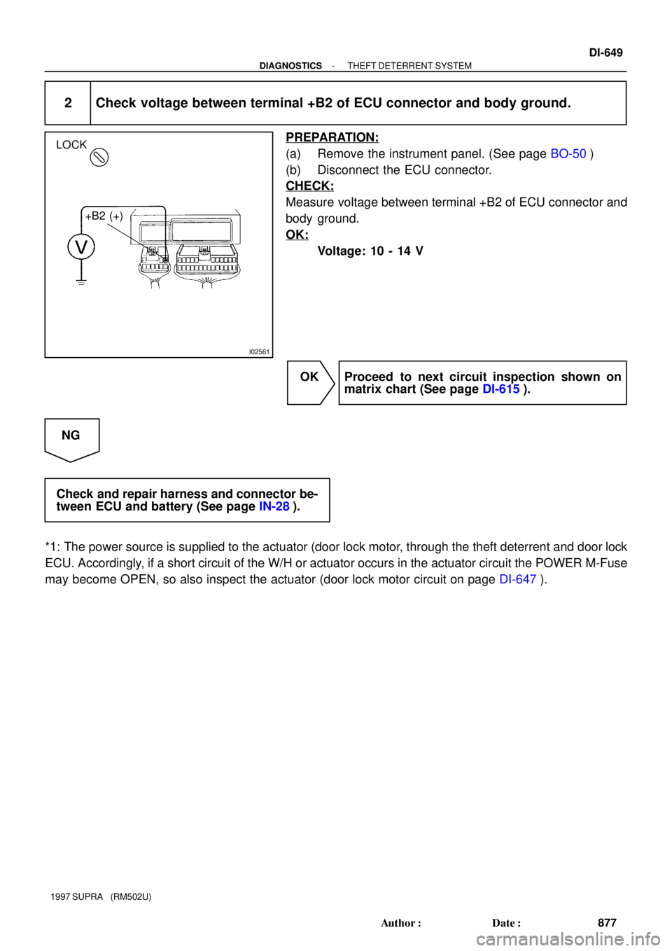
I02561
LOCK
+B2 (+)
- DIAGNOSTICSTHEFT DETERRENT SYSTEM
DI-649
877 Author�: Date�:
1997 SUPRA (RM502U)
2 Check voltage between terminal +B2 of ECU connector and body ground.
PREPARATION:
(a) Remove the instrument panel. (See page BO-50)
(b) Disconnect the ECU connector.
CHECK:
Measure voltage between terminal +B2 of ECU connector and
body ground.
OK:
Voltage: 10 - 14 V
OK Proceed to next circuit inspection shown on
matrix chart (See page DI-615).
NG
Check and repair harness and connector be-
tween ECU and battery (See page IN-28).
*1: The power source is supplied to the actuator (door lock motor, through the theft deterrent and door lock
ECU. Accordingly, if a short circuit of the W/H or actuator occurs in the actuator circuit the POWER M-Fuse
may become OPEN, so also inspect the actuator (door lock motor circuit on page DI-647).