Page 909 of 1807
I02538
10 (+)9 (-)
DI-618
- DIAGNOSTICSTHEFT DETERRENT SYSTEM
846 Author�: Date�:
1997 SUPRA (RM502U)
INSPECTION PROCEDURE
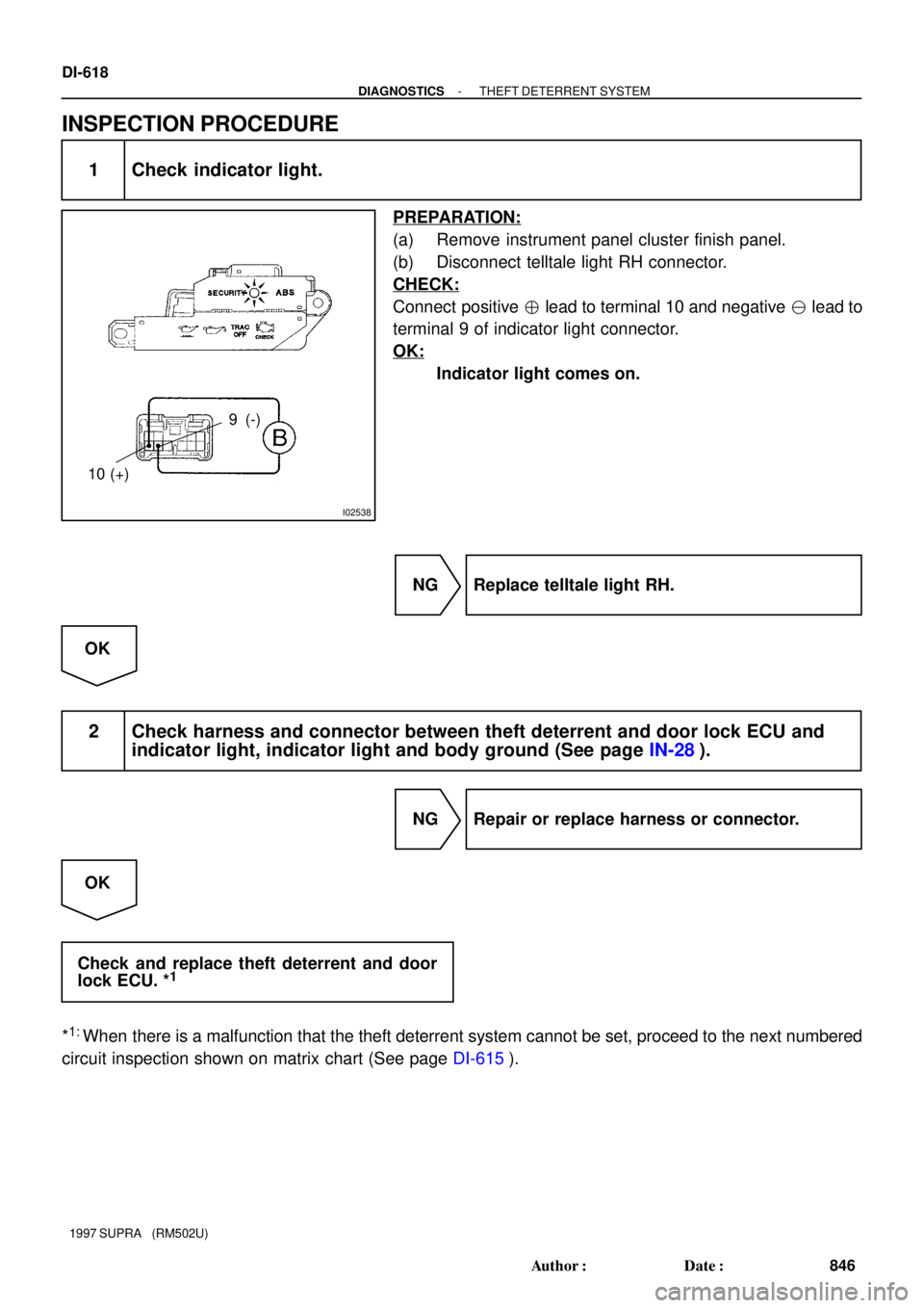
1 Check indicator light.
PREPARATION:
(a) Remove instrument panel cluster finish panel.
(b) Disconnect telltale light RH connector.
CHECK:
Connect positive � lead to terminal 10 and negative � lead to
terminal 9 of indicator light connector.
OK:
Indicator light comes on.
NG Replace telltale light RH.
OK
2 Check harness and connector between theft deterrent and door lock ECU and
indicator light, indicator light and body ground (See page IN-28).
NG Repair or replace harness or connector.
OK
Check and replace theft deterrent and door
lock ECU. *
1
*1:
When there is a malfunction that the theft deterrent system cannot be set, proceed to the next numbered
circuit inspection shown on matrix chart (See page DI-615).
Page 910 of 1807
N19900
1K
1J
IJ2P2P2
C9C9IJ1
EA122
2IB2IF2
I19I19IB1
2
2A
S2S3 4
6
87 B1365
1223
1
2
3510Theft Deterrent and
Door Lock ECU
EA2
EA3
4Starter Relay MAINL-OSRLY
25
Clutch Start Switch(M/T)
21AM2 J/B No.1 STR/B No.2
2
1
2JZ-GTE
2JZ-GE
Battery1
2 B
BL-O
L-O B-WB-WW-R
W-R W-B
B
B B 1 Ignition
SwitchT13
Park/Neutral Start Switch
1
1 B
(A/T)
12
- DIAGNOSTICSTHEFT DETERRENT SYSTEM
DI-619
847 Author�: Date�:
1997 SUPRA (RM502U)
Starter Relay Circuit
CIRCUIT DESCRIPTION
When the theft deterrent system is activated, contact ºaº in the ECU becomes open, creating an open circuit
in terminal ST circuit and making the starter inoperative (starter cut).
In this condition, if one of the following operations is done, the contact ºaº in the ECU is grounded, thus can-
celing the starter cut:
(1) The front LH and RH door is unlocked with a key.
WIRING DIAGRAM
DI4X2-01
Page 911 of 1807
I02540
START
Disconnect
SPLY (+)
DI-620
- DIAGNOSTICSTHEFT DETERRENT SYSTEM
848 Author�: Date�:
1997 SUPRA (RM502U)
INSPECTION PROCEDURE
HINT:
This troubleshooting is based on the premise that engine cranking occurs.
If the engine does not crank, proceed to the engine troubleshooting on page DI-3 or DI-141 (Vol. 1).
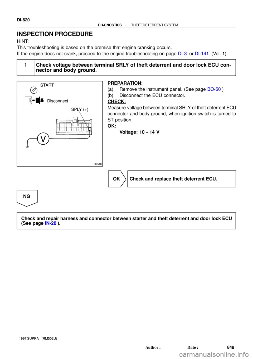
1 Check voltage between terminal SRLY of theft deterrent and door lock ECU con-
nector and body ground.
PREPARATION:
(a) Remove the instrument panel. (See page BO-50)
(b) Disconnect the ECU connector.
CHECK:
Measure voltage between terminal SRLY of theft deterrent ECU
connector and body ground, when ignition switch is turned to
ST position.
OK:
Voltage: 10 - 14 V
OK Check and replace theft deterrent ECU.
NG
Check and repair harness and connector between starter and theft deterrent and door lock ECU
(See page IN-28).
Page 912 of 1807
I02710
I02710
Theft Deterrent and
Door Lock ECU R/B No.2
HORN Relay
R/B No2.Horn Switch
HornL-R
L-B HAZ-HORN
BatteryHORN
L-BL-R
L-R W
22
2 2
2
2A 11
1116
14
L-R
L-B 3IB2IF2
24
BT13
- DIAGNOSTICSTHEFT DETERRENT SYSTEM
DI-621
849 Author�: Date�:
1997 SUPRA (RM502U)
Horn Relay Circuit
CIRCUIT DESCRIPTION
When the theft deterrent system is activated, it causes the Tr in the ECU to switch on and off in approximately
0.2 sec. cycles. This switches the horn relay on and off, thus the horn blow (See the wiring diagram below).
In this condition, if any of the following operations is done, the Tr in the ECU goes off and the horn relay
switches off, thus the horns stop blowing:
(1) The front LH or RH door is unlocked with a key.
(2) The ignition switch is turned to the ACC or ON position.
(3) Approximately 1 minute elapses.
WIRING DIAGRAM
DI4X3-01
Page 913 of 1807
I02711
LOCK
Disconnect
HORN (+)
DI-622
- DIAGNOSTICSTHEFT DETERRENT SYSTEM
850 Author�: Date�:
1997 SUPRA (RM502U)
INSPECTION PROCEDURE
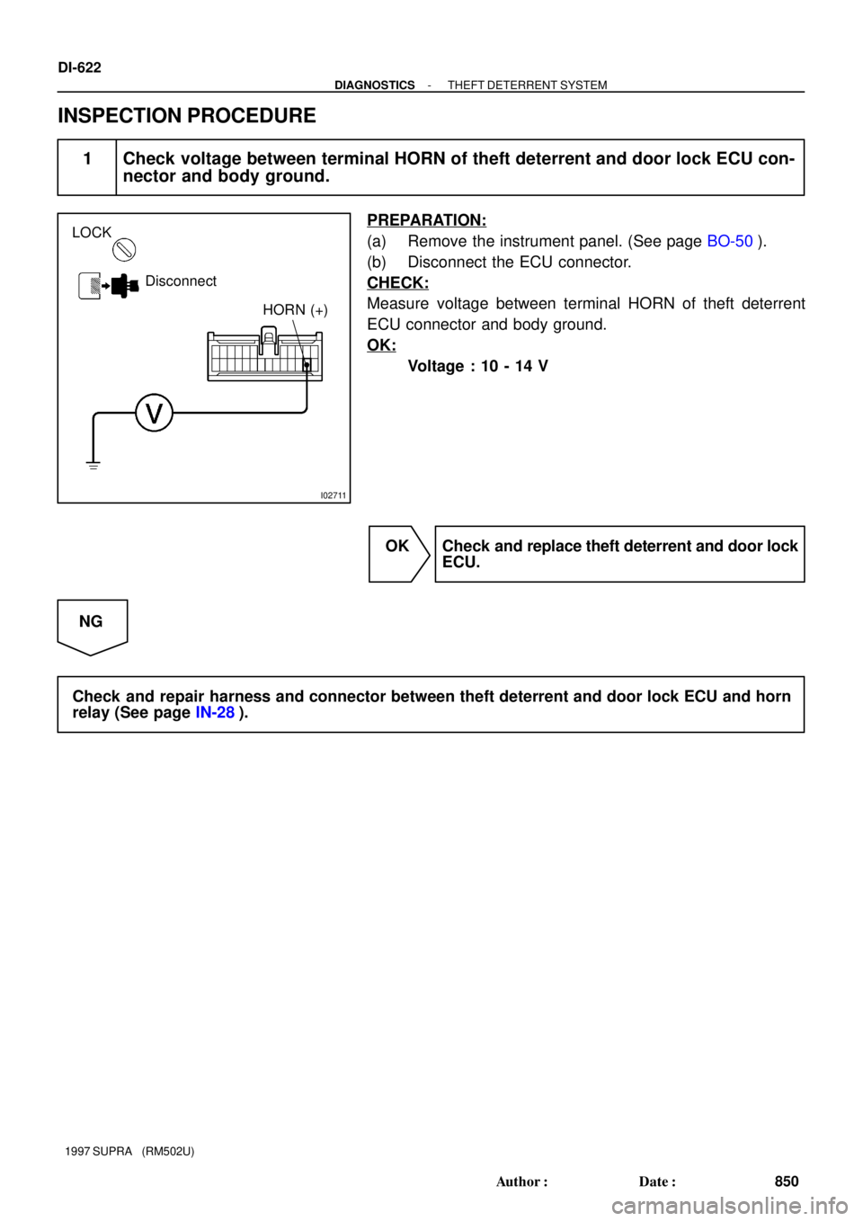
1 Check voltage between terminal HORN of theft deterrent and door lock ECU con-
nector and body ground.
PREPARATION:
(a) Remove the instrument panel. (See page BO-50).
(b) Disconnect the ECU connector.
CHECK:
Measure voltage between terminal HORN of theft deterrent
ECU connector and body ground.
OK:
Voltage : 10 - 14 V
OK Check and replace theft deterrent and door lock
ECU.
NG
Check and repair harness and connector between theft deterrent and door lock ECU and horn
relay (See page IN-28).
Page 914 of 1807
N09783
2
2AEA1II1
IB6 IF219 622
7
1
2
1
BatteryR/B No.2
HAZ-HORNW
(2JZ-GE)Theft Deterrent and
Door Lock ECU T13
(2JZ-GE)
11
(2JZ-GTE)
Theft Deterrent
Horn (2JZ-GTE)
BP-B W
WW-LW-L
SHa
b P-B
W-L
- DIAGNOSTICSTHEFT DETERRENT SYSTEM
DI-623
851 Author�: Date�:
1997 SUPRA (RM502U)
Theft Deterrent Horn Circuit
CIRCUIT DESCRIPTION
When the theft deterrent system is activated, contact ºaº and contact ºbº in the ECU close alternately in cycles
of approximately 0.2 sec., causing the theft deterrent horn to blow (See the wiring diagram below).
In this condition, if any of the following operations is done, the contact ºaº in the ECU opens, thus stopping
the theft deterrent horn from blowing:
(1) The front LH or RH door is unlocked with a key.
(2) The ignition switch is turned to the ACC or ON position.
(3) Approximately 1 minute elapses.
WIRING DIAGRAM
DI4X4-01
Page 915 of 1807
I02542
LOCK
Disconnect
2JZ-GE
2JZ-GTE2 (+)
2 (+)
N14682
1 (+)
2 (-)
DI-624
- DIAGNOSTICSTHEFT DETERRENT SYSTEM
852 Author�: Date�:
1997 SUPRA (RM502U)
INSPECTION PROCEDURE
1 Check voltage between terminal SH of theft deterrent horn connector and body
ground.
PREPARATION:
Remove the theft deterrent horn and disconnect the connector.
CHECK:
Measure voltage between terminal 1 of theft deterrent horn
connector and body ground.
OK:
Voltage : 10 - 14 V
NG Check and repair harness and connector be-
tween HORN fuse and theft deterrent horn.
OK
2 Check theft deterrent horn.
CHECK:
Connect positive � lead to terminal 1 and negative � lead to
terminal 2 of theft deterrent horn connector.
OK:
Theft deterrent horn blows.
NG Replace theft deterrent horn.
OK
Page 916 of 1807
- DIAGNOSTICSTHEFT DETERRENT SYSTEM
DI-625
853 Author�: Date�:
1997 SUPRA (RM502U)
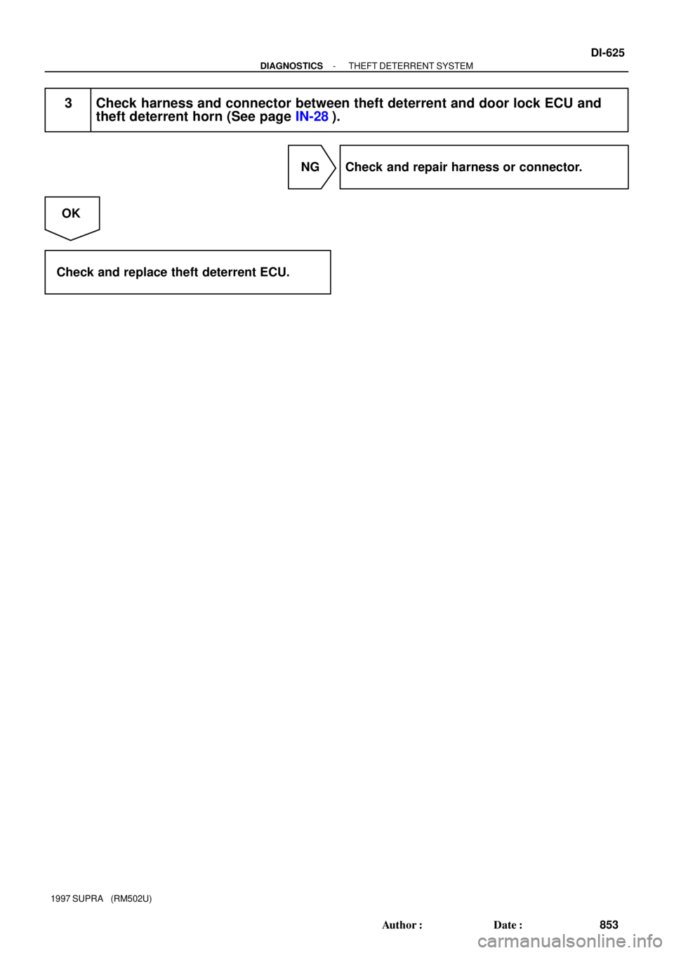
3 Check harness and connector between theft deterrent and door lock ECU and
theft deterrent horn (See page IN-28).
NG Check and repair harness or connector.
OK
Check and replace theft deterrent ECU.

21AM2 J/B No.1")

Theft Deterrent and
Door Lock ECU T13
(2JZ-GE)
11
(2JZ-GTE)
Theft Deterrent
Horn (2JZ-GTE)
BP-B W
WW-LW-L
SHa
b P-B
W-L
- DIAG")