Page 789 of 1807
F03363
DI-498
- DIAGNOSTICSANTI-LOCK BRAKE SYSTEM
726 Author�: Date�:
1997 SUPRA (RM502U)
Check for Fluid Leakage
Check for fluid leakage from actuators or hydraulic lines.
DI4VO-01
Page 801 of 1807
F03369
R/B No.2
TRAC
F03370BE6053F06762
LOCK
R/B No.5
(-) (+)
DI-510
- DIAGNOSTICSABS & TRACTION CONTROL SYSTEM
738 Author�: Date�:
1997 SUPRA (RM502U)
INSPECTION PROCEDURE
1 Check TRAC fuse.
PREPARATION:
Remove TRAC fuse from R/B No.2.
CHECK:
Check continuity of TRAC fuse.
OK:
Continuity
NG Check for short in all harness and components
connected to TRAC fuse.
OK
2 Check voltage between terminal 1 of R/B No.5 (for throttle control relay).
PREPARATION:
Remove throttle control relay from P/B No.5.
CHECK:
Measure voltage between terminal 1 of R/B No.5 (for throttle
control relay).
OK:
Voltage: 10 - 14 V
NG Repair or replace harness or connector.
OK
Page 828 of 1807
BE6653F03397F03398
LOCK
E01
- DIAGNOSTICSABS & TRACTION CONTROL SYSTEM
DI-537
765 Author�: Date�:
1997 SUPRA (RM502U)
4 Check continuity between terminal E01 of throttle control ECU connector and
body ground.
CHECK:
Measure resistance between terminal E01 of throttle control
ECU connector and body ground.
OK:
Resistance: 1 W or less
NG Repair or replace harness or connector.
OK
Check for open in harness and connector between throttle control ECU and battery
(See page IN-28).
Page 854 of 1807
DI4WJ-01
- DIAGNOSTICSSUPPLEMENTAL RESTRAINT SYSTEM
DI-563
791 Author�: Date�:
1997 SUPRA (RM502U)
PROBLEM SYMPTOMS TABLE
Proceed with troubleshooting of each circuit in the table below.
Problem SymptomInspection ItemPage
�WIth the ignition switch at ACC or ON, the SRS warning light
sometimes lights up after approx. 6 seconds have elapsed.
�SRS warning light lights up even when ignition switch is in the
LOCK position.
�SRS warning light system malfunction (Always lit up when
ignition switch is in LOCK position.)DI-598
�WIth the ignition switch at ACC or ON, the SRS warning light
does not light up.�SRS warning light system malfunction (Does not light up
when ignition switch is turned to ACC or ON.)DI-600
�DTC not displayed.
�SRS warning light is always lit up with a DTC check procedure.
�DTC displayed without Tc and E
1 terminal connection.
�Tc terminal circuitDI-603
Page 858 of 1807

AB0069R05902AB0118AB0119AB0057
AB0069
N19819H07911
P squibAirbag Sensor
Assembly
D squibSpiral
Cable
ACC
ON
or
E
1Tc DLC1
Code 11
P+P-
D+D-
- DIAGNOSTICSSUPPLEMENTAL RESTRAINT SYSTEM
DI-567
795 Author�: Date�:
1997 SUPRA (RM502U)
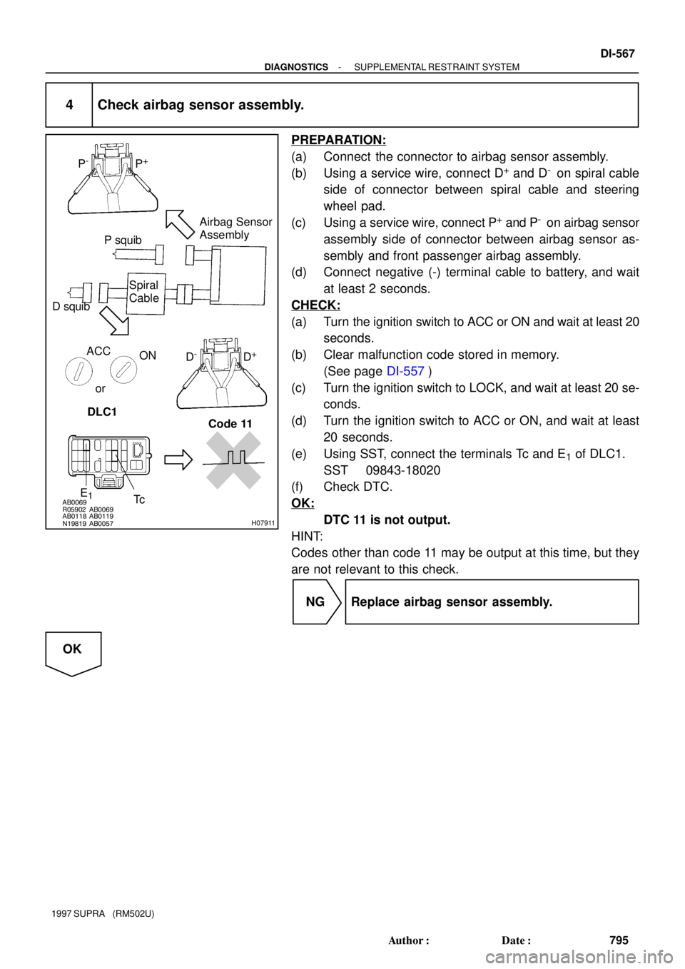
4 Check airbag sensor assembly.
PREPARATION:
(a) Connect the connector to airbag sensor assembly.
(b) Using a service wire, connect D
+ and D- on spiral cable
side of connector between spiral cable and steering
wheel pad.
(c) Using a service wire, connect P
+ and P- on airbag sensor
assembly side of connector between airbag sensor as-
sembly and front passenger airbag assembly.
(d) Connect negative (-) terminal cable to battery, and wait
at least 2 seconds.
CHECK:
(a) Turn the ignition switch to ACC or ON and wait at least 20
seconds.
(b) Clear malfunction code stored in memory.
(See page DI-557)
(c) Turn the ignition switch to LOCK, and wait at least 20 se-
conds.
(d) Turn the ignition switch to ACC or ON, and wait at least
20 seconds.
(e) Using SST, connect the terminals Tc and E
1 of DLC1.
SST 09843-18020
(f) Check DTC.
OK:
DTC 11 is not output.
HINT:
Codes other than code 11 may be output at this time, but they
are not relevant to this check.
NG Replace airbag sensor assembly.
OK
Page 859 of 1807

H03221
P squibAirbag Sensor
Assembly
D squib
Spiral
Cable
ACC
ON
E
1Tc DLC1 Code 11or
DI-568
- DIAGNOSTICSSUPPLEMENTAL RESTRAINT SYSTEM
796 Author�: Date�:
1997 SUPRA (RM502U)
5 Check D squib.
PREPARATION:
(a) Turn the ignition switch to LOCK.
(b) Disconnect negative (-) terminal cable from the battery,
and wait at least 90 seconds.
(c) Connect the steering wheel pad connector.
(d) Connect negative (-) terminal cable to battery, and wait
at least 2 seconds.
CHECK:
(a) Turn the ignition switch to ACC or ON and wait at least 20
seconds.
(b) Clear malfunction code stored in memory.
(See page DI-557)
(c) Turn the ignition switch to LOCK, and wait at least 20 se-
conds.
(d) Turn the ignition switch to ACC or ON, and wait at least
20 seconds.
(e) Using SST, connect the terminals Tc and E
1 of DLC1.
SST 09843-18020
(f) Check DTC.
OK:
DTC 11 is not output.
HINT:
Codes other than code 11 may be output at this time, but they
are not relevant to this check.
NG Replace steering wheel pad.
OK
Page 860 of 1807

H03222
P squib
Spiral
Cable
ACC
ON
E
1Tc DLC1 Code 11orAirbag Sensor
Assembly
D squib
- DIAGNOSTICSSUPPLEMENTAL RESTRAINT SYSTEM
DI-569
797 Author�: Date�:
1997 SUPRA (RM502U)
6 Check P squib.
PREPARATION:
(a) Turn the ignition switch to LOCK.
(b) Disconnect negative (-) terminal cable from the battery,
and wait at least 90 seconds.
(c) Connect the front passenger airbag assembly connector.
(d) Connect negative (-) terminal cable to battery, and wait
at least 2 seconds.
CHECK:
(a) Turn the ignition switch to ACC or ON, and wait at least
20 seconds.
(b) Clear malfunction code stored in memory.
(See page DI-557)
(c) Turn the ignition switch to LOCK, and wait at least 20 se-
conds.
(d) Turn the ignition switch to ACC or ON, and wait at least
20 seconds.
(e) Using SST, connect the terminals Tc and E
1 of DLC1.
SST 09843-18020
(f) Check DTC.
OK:
DTC 11 is not output.
HINT:
Codes other than code 11 may be output at this time, but they
are not relevant to this check.
NG Replace front passenger airbag assembly.
OK
From the results of the above inspection, the malfunctioning part can now be considered normal.
To make sure of this, use the simulation method to check. If the malfunctioning part can not be
detected by the simulation method, replace all SRS components including the wire harness.
Page 864 of 1807

AB0069R05902AB0069AB0118AB0119FI1389N19819H07915
P squibAirbag Sensor
Assembly
D squib
Spiral
Cable
ACC
ON
or
E
1
Tc DLC1
Code 12
P+P-
D+D-
- DIAGNOSTICSSUPPLEMENTAL RESTRAINT SYSTEM
DI-573
801 Author�: Date�:
1997 SUPRA (RM502U)
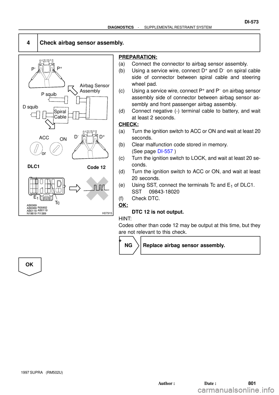
4 Check airbag sensor assembly.
PREPARATION:
(a) Connect the connector to airbag sensor assembly.
(b) Using a service wire, connect D
+ and D- on spiral cable
side of connector between spiral cable and steering
wheel pad.
(c) Using a service wire, connect P
+ and P- on airbag sensor
assembly side of connector between airbag sensor as-
sembly and front passenger airbag assembly.
(d) Connect negative (-) terminal cable to battery, and wait
at least 2 seconds.
CHECK:
(a) Turn the ignition switch to ACC or ON and wait at least 20
seconds.
(b) Clear malfunction code stored in memory.
(See page DI-557)
(c) Turn the ignition switch to LOCK, and wait at least 20 se-
conds.
(d) Turn the ignition switch to ACC or ON, and wait at least
20 seconds.
(e) Using SST, connect the terminals Tc and E
1 of DLC1.
SST 09843-18020
(f) Check DTC.
OK:
DTC 12 is not output.
HINT:
Codes other than code 12 may be output at this time, but they
are not relevant to this check.
+
NG Replace airbag sensor assembly.
OK