Page 773 of 1807
F03341
R/B No.2J/B No.1Stop Light
SwitchABS ECU
125
Light
Failure
Sensor
Stop LightJ/B
No.11
10IH
IC
A18 A22 *1*2
G-WG-W
G-W1
2 W STOP
210
1B 1I W-LPOWER
22 W
2
2A
ALTR/B No.2
B
Battery
NORMAL ABS (2JZ-GE Engine)
SPORT ABS (2JS-GTE Engine)
*1:
*2:
1
DI-482
- DIAGNOSTICSANTI-LOCK BRAKE SYSTEM
710 Author�: Date�:
1997 SUPRA (RM502U)
DTC 49 Stop Light Switch Circuit
CIRCUIT DESCRIPTION
This stop light switch senses whether the brake pedal is depressed or released, and sends a signal to the
ECU.
DTC No.DTC Detecting ConditionTrouble Area
491.2 - 1.7 V of STP voltage is continued for 0.3 sec. or more.�Open in stop light circuit
WIRING DIAGRAM
INSPECTION PROCEDURE
1 Check operation of stop light.
CHECK:
Check that stop light lights up when brake pedal is depressed and turns off when brake pedal is released.
NG Replace stop light bulb.
OK
DI4VI-01
Page 774 of 1807
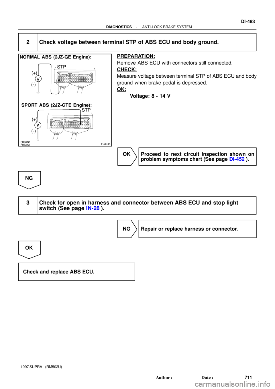
F03342F03343F03344
NORMAL ABS (2JZ-GE Engine):
SPORT ABS (2JZ-GTE Engine):V (+)
(-)
(+)
(-)STP
STP
- DIAGNOSTICSANTI-LOCK BRAKE SYSTEM
DI-483
711 Author�: Date�:
1997 SUPRA (RM502U)
2 Check voltage between terminal STP of ABS ECU and body ground.
PREPARATION:
Remove ABS ECU with connectors still connected.
CHECK:
Measure voltage between terminal STP of ABS ECU and body
ground when brake pedal is depressed.
OK:
Voltage: 8 - 14 V
OK Proceed to next circuit inspection shown on
problem symptoms chart (See page DI-452).
NG
3 Check for open in harness and connector between ABS ECU and stop light
switch (See page IN-28).
NG Repair or replace harness or connector.
OK
Check and replace ABS ECU.
Page 775 of 1807
DI-484
- DIAGNOSTICSANTI-LOCK BRAKE SYSTEM
712 Author�: Date�:
1997 SUPRA (RM502U)
DTC 51 ABS Pump Motor Lock
CIRCUIT DESCRIPTION
DTC No.DTC Detecting ConditionTrouble Area
51Pump motor is not operating normally during initial check.�ABS pump motor
Fail safe function:
If trouble occurs in the ABS pump motor, the ECU cuts off the current to the ABS solenoid relay and prohibits
ABS control.
WIRING DIAGRAM
See page DI-460.
INSPECTION PROCEDURE
See inspection of ABS actuator (See page BR-66 or BR-66).
DI4VJ-01
Page 776 of 1807
F03345
R/B No.2ABS ECU*1
*2
W21B22
B
Battery
NORMAL ABS (2JZ-GE Engine)
SPORT ABS (2JZ-GTE Engine)
*1:
*2:
ALTW
R/B No.2
J/B No.12AM1 W1J
442
IG Switch
4 B-Y
J/B No.1
1J1KECU-IG513A18A20 213
212
1325IG 1
GND1
GND2 A20
A20 A19
A19 W-B
W-B W-B
W-B
W-B
*2IE IG
- DIAGNOSTICSANTI-LOCK BRAKE SYSTEM
DI-485
713 Author�: Date�:
1997 SUPRA (RM502U)
DTC Always ON Malfunction in ECU IG Power Source
Circuit
CIRCUIT DESCRIPTION
This is the power source for the ECU, hence the CPU, and the actuators.
DTC No.DTC Detecting ConditionTrouble Area
Always ONVoltage of ECU terminal IG1 remains at more than 17 V for 1
sec. or more.
�Battery
�IC regulator
�Open or short in power source circuit
�ECU
Fail safe function:
If trouble occurs in the power source circuit, the ECU cuts off current to the ABS solenoid relay and prohibits
ABS control.
WIRING DIAGRAM
DI4VK-01
Page 777 of 1807
DI-486
- DIAGNOSTICSANTI-LOCK BRAKE SYSTEM
714 Author�: Date�:
1997 SUPRA (RM502U)
INSPECTION PROCEDURE
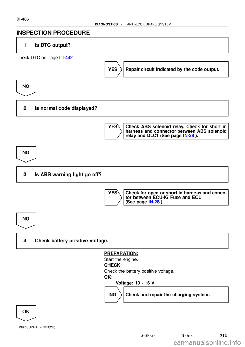
1 Is DTC output?
Check DTC on page DI-442.
YES Repair circuit indicated by the code output.
NO
2 Is normal code displayed?
YES Check ABS solenoid relay. Check for short in
harness and connector between ABS solenoid
relay and DLC1 (See page IN-28).
NO
3 Is ABS warning light go off?
YES Check for open or short in harness and conec-
tor between ECU-IG Fuse and ECU
(See page IN-28).
NO
4 Check battery positive voltage.
PREPARATION:
Start the engine.
CHECK:
Check the battery positive voltage.
OK:
Voltage: 10 - 16 V
NG Check and repair the charging system.
OK
Page 778 of 1807
- DIAGNOSTICSANTI-LOCK BRAKE SYSTEM
DI-487
715 Author�: Date�:
1997 SUPRA (RM502U)
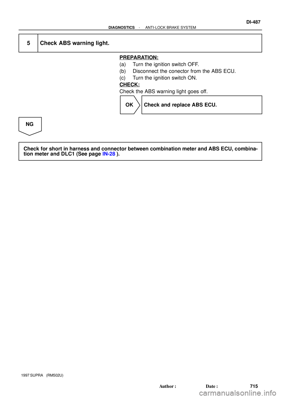
5 Check ABS warning light.
PREPARATION:
(a) Turn the ignition switch OFF.
(b) Disconnect the conector from the ABS ECU.
(c) Turn the ignition switch ON.
CHECK:
Check the ABS warning light goes off.
OK Check and replace ABS ECU.
NG
Check for short in harness and connector between combination meter and ABS ECU, combina-
tion meter and DLC1 (See page IN-28).
Page 779 of 1807
F03346F03347F03348
2JZ-GE Engine (NORMAL ABS):
2JZ-GTE Engine (SPORT ABS):Battery
ABS Control RelayJ/B No.1
(Motor
Relay)
(Solenoid
Relay)
W-B
1
2
6
A9
4
3
1
4
A9B-R
EA1
6
23 B-R
22
DLC1 Short Pin
L16
IJ1
A18
4
LLL
IF212
L42
ABS
Warning
Light
Y
GAUGE
ABS ECU1J1E
512
25
ABS ActuatorABS ECU
12 V
WA
EA
Battery
R/B No.5
ABS
Solenoid Relay15
5
5555 26
4
5 3
W-B
EA
ABS Actuator
B-R
EA16
23 B-R
Short Pin
DLC1
22L16
IJ1L
L
L11A20WA12 V ABS ECU
ABS
Warning
Light
L4
IF212
2 Y
GAUGE J/B No.1
1J
1E
12 5
ABS & TRAC
ECU DI-488
- DIAGNOSTICSANTI-LOCK BRAKE SYSTEM
716 Author�: Date�:
1997 SUPRA (RM502U)
ABS Warning Light Circuit
CIRCUIT DESCRIPTION
If the ECU detects trouble, it lights the ABS warning light while at the same time prohibiting ABS control. At
this time, the ECU records a DTC in memory.
After removing the short pin of the DLC1, connect terminals Tc and E1 of the DLC1 or DLC2 to make the
ABS warning light to blink and output the DTC.
WIRING DIAGRAM
DI4VL-01
Page 780 of 1807

(-) LOCK
- DIAGNOSTICSANTI-LOCK BRAKE SYSTEM
DI-489
717 Author�: Date�:
1997 SUPRA (RM502U)
INSPECT")
F02629F03349F03350
LOCK
Open
ContinuityA8A9
Continuity
F02629F03351F03352
OpenContinuity
A8 A9
(+)
(-) LOCK
- DIAGNOSTICSANTI-LOCK BRAKE SYSTEM
DI-489
717 Author�: Date�:
1997 SUPRA (RM502U)
INSPECTION PROCEDURE
2JZ-GE Engine:
Troubleshooting in accordance with the chart below for each trouble symptom.
ABS warning light does not light upGo to step 1
ABS warning light remains onGo to step 3
1 Check ABS warning light.
See Combination Meter Troubleshooting on page BE-2.
NG Replace bulb or combination meter assembly.
OK
2 Check ABS control (solenoid) relay.
PREPARATION:
Disconnect the connectors from ABS control (solenoid) relay.
CHECK:
Check continuity between each terminal of ABS control (sole-
noid) relay.
OK:
Terminals A9 - 1 and A8 - 3Continuity (Reference value 80 W)
Terminals A9 - 5 and A9 - 6Continuity
Terminals A9 - 2 and A9 - 5Open
CHECK:
(a) Apply battery positive voltage between terminals A9 - 1
and A8 - 3.
(b) Check continuity between each terminal of ABS solenoid
relay.
OK:
Terminals A9 - 5 and A9 - 6Open
Terminals A9 - 2 and A9 - 5Continuity


SPORT ABS (2JZ-GTE Engine)
*1:
*2:
ALTW
R/B No.2
J/B No.12AM1 W1J
442
IG Switch
4 B-Y
J/B No.1
1J1KECU-IG513A18A20 213
212
1325I")
:
2JZ-GTE Engine (SPORT ABS):Battery
ABS Control RelayJ/B No.1
(Motor
Relay)
(Solenoid
Relay)
W-B
1
2
6
A9
4
3
1
4
A9B-R
EA1
6
23 B-R
22
DLC1 Short Pin
L1")