Page 1345 of 1807

P10820
Adhesive
P13197
Oil Pressure
SwitchKnock Sensor
- ENGINE MECHANICAL (2JZ-GTE)CYLINDER BLOCK
EM-93
1198 Author�: Date�:
1997 SUPRA (RM502U)
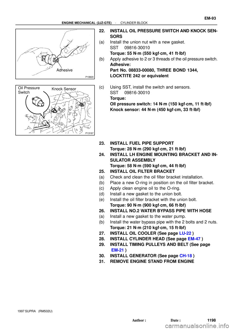
22. INSTALL OIL PRESSURE SWITCH AND KNOCK SEN-
SORS
(a) Install the union nut with a new gasket.
SST 09816-30010
Torque: 55 N´m (550 kgf´cm, 41 ft´lbf)
(b) Apply adhesive to 2 or 3 threads of the oil pressure switch.
Adhesive:
Part No. 08833-00080, THREE BOND 1344,
LOCKTITE 242 or equivalent
(c) Using SST, install the switch and sensors.
SST 09816-30010
Torque:
OIl pressure switch: 14 N´m (150 kgf´cm, 11 ft´lbf)
Knock sensor: 44 N´m (450 kgf´cm, 33 ft´lbf)
23. INSTALL FUEL PIPE SUPPORT
Torque: 28 N´m (290 kgf´cm, 21 ft´lbf)
24. INSTALL LH ENGINE MOUNTING BRACKET AND IN-
SULATOR ASSEMBLY
Torque: 58 N´m (590 kgf´cm, 44 ft´lbf)
25. INSTALL OIL FILTER BRACKET
(a) Check and clean the oil filter bracket installation.
(b) Place a new O-ring in position on the oil filter bracket.
(c) Apply clean engine oil to the O-ring.
(d) Install a new gasket to the union bolt.
(e) Install the oil filter bracket with the union bolt.
Torque: 90 N´m (900 kgf´cm, 66 ft´lbf)
26. INSTALL NO.2 WATER BYPASS PIPE WITH HOSE
(a) Install a new gasket to the water pump.
(b) Install the water bypass pipe with the 2 bolts and 2 nuts.
Torque: 21 N´m (210 kgf´cm, 15 ft´lbf)
27. INSTALL OIL COOLER (See page LU-22)
28. INSTALL CYLINDER HEAD (See page EM-47)
29. INSTALL TIMING PULLEYS AND BELT (See page
EM-21)
30. INSTALL GENERATOR (See page CH-18)
31. REMOVE ENGINE STAND FROM ENGINE
Page 1346 of 1807
Z16724
8
8
5
47 63
2 1
M/T
Z16725
M/T
90°
Painted Mark 90°
Z16739
A/T
Rear Plate
Z16736
A/T
1
2
34
56
7 8 EM-94
- ENGINE MECHANICAL (2JZ-GTE)CYLINDER BLOCK
1199 Author�: Date�:
1997 SUPRA (RM502U)
32. M/T:
INSTALL FLYWHEEL
HINT:
The flywheel bolts are tightened in 2 progressive step, (b) and
(d).
(a) Install the flywheel on the crankshaft.
(b) Install and uniformly tighten the 8 bolts, in several passes,
in the sequence shown.
Torque: 49 N´m (500 kgf´cm, 36 ft´lbf)
(c) Mark the flywheel bolt with paint.
(d) Retighten the flywheel bolts by an additional 90°.
(e) Check that the painted mark is now at a 90° angle to (d).
33. A/T:
INSTALL DRIVE PLATE
(a) Install the front spacer, drive plate and rear plate on the
crankshaft.
(b) Apply adhesive to 2 or 3 threads of the mounting bolt end.
Adhesive:
Part No. 08833-00070, THREE BOND 1324 or
equivalent
(c) Install and uniformly tighten the 8 bolts, in several passes,
in the sequence shown.
Torque: 83 N´m (850 kgf´cm, 61 ft´lbf)
Page 1348 of 1807
PP0QF-01
PP-12
- PREPARATIONENGINE MECHANICAL (2JZ-GTE)
58 Author�: Date�:
1997 SUPRA (RM502U)
EQUIPMENT
OBDII scan toolEngine speed
Caliper gauge
CO/HC meter
Compression gauge
Connecting rod aligner
Cylinder gauge
Dial indicator
Dye penetrant
Engine tune-up tester
Heater
Micrometer
Mirror
Magnetic finger
Piston ring compressor
Piston ring expander
Plastigage
Precision straight edge
Spring testerValve spring
Steel squareValve spring
Thermometer
Torque wrench
Valve seat cutter
Vernier calipers
V-block
Page 1360 of 1807

EM0494
P11926
SST (B)
SST (A)
P11777
Seal Packing
- ENGINE MECHANICAL (2JZ-GTE)VALVE CLEARANCE
EM-7
111 2 Author�: Date�:
1997 SUPRA (RM502U)
(b) Determine the replacement adjusting shim size according
to the following Formula or Charts:
�Using a micrometer, measure the thickness of the
removed shim.
�Calculate the thickness of a new shim so the valve
clearance comes within specified value.
T .......... Thickness of used shim
A .......... Measured valve clearance
N .......... Thickness of new shim
Intake
N = T + (A - 0.20 mm (0.008 in.))
Exhaust
N = T + (A - 0.30 mm (0.012 in.))
�Select a new shim with a thickness as close as pos-
sible to the calculated values.
HINT:
Shims are available in 17 sizes in increments of 0.050 mm
(0.0020 in.), from 2.500 mm (0.0984 in.) to 3.300 mm (0.1299
in.).
(c) Install a new adjusting shim.
�Place a new adjusting shim on the valve lifter, with
imprinted numbers facing down.
�Press down the valve lifter with SST (A), and re-
move SST (B).
SST 09248-55040
(d) Recheck the valve clearance.
9. REINSTALL NO.1 AND NO.2 CYLINDER HEAD COV-
ERS
(a) Remove any old packing (FIPG) material.
(b) Apply seal packing to the cylinder head as shown in the
illustration.
Seal packing:
Part No. 08826-00080 or equivalent
(c) Install the gaskets to the No.1 and No.2 cylinder head
covers.
(d) Install the 12 seal washers to the bolts.
(e) Install the No.2 cylinder head cover with the 6 bolts, 4 seal
washers and 4 nuts..
Torque: 5.4 N´m (55 kgf´cm, 48 in.´lbf)
(f) Install the No.1 cylinder head cover with the 6 bolts, 4 seal
washers and 4 nuts..
Torque: 5.4 N´m (55 kgf´cm, 48 in.´lbf)
(g) Connect the 2 PCV hoses to the cylinder head covers.
(h) Install the bolt holding the VSV to the turbo outlet duct.
(i) Connect the cruise control actuator cable to the cable
bracket.
Page 1364 of 1807

EM0AF-02
A02173
Sensor
Inward
Part
P18867
A02168
10 mm
Hexagon WrenchAdhesive
A02171
A02172
- ENGINE MECHANICAL (2JZ-GTE)TIMING BELT
EM-21
1126 Author�: Date�:
1997 SUPRA (RM502U)
INSTALLATION
1. INSTALL CRANKSHAFT TIMING PULLEY
(a) Align the pulley set key with the key groove of the pulley.
(b) Slide on the timing pulley facing the flange side inward.
NOTICE:
Do not scratch the sensor part of the crankshaft timing
pulley.
(c) Install the timing belt plate with the bolt.
Torque: 7.8 N´m (80 kgf´cm, 69 in.´lbf)
2. INSTALL IDLER PULLEY
(a) Apply adhesive to 2 or 3 threads of the pivot bolt.
Adhesive:
Part No. 08833-00080, THREE BOND 1344,
LOCTITE 242 or equivalent
(b) Using a 10 mm hexagon wrench, install the plate washer
and pulley with the pivot bolt.
Torque: 35 N´m (350 kgf´cm, 26 ft´lbf)
(c) Check that the pulley bracket moves smoothly.
3. TEMPORARILY INSTALL TIMING BELT
NOTICE:
The engine should be cold.
(a) Using the crankshaft pulley bolt, turn the crankshaft, and
align the timing marks on the crankshaft timing pulley and
on the oil pump body.
(b) Remove any oil or water on the crankshaft timing pulley
and idler pulley, and keep them clean.
(c) Install the timing belt on the crankshaft timing pulley and
idler pulley.
HINT:
(When re-using timing belt):
Align the match marks of the crankshaft timing pulley and timing
belt, and install the belt with the arrow pointing in the direction
of engine revolution.
Page 1365 of 1807

S00263
S00268
SST
SST
P03960
A02559
SST
S00394
EM-22
- ENGINE MECHANICAL (2JZ-GTE)TIMING BELT
1127 Author�: Date�:
1997 SUPRA (RM502U)
4. INSTALL TIMING BELT GUIDE
Install the guide, facing the cup side outward.
5. INSTALL NO.1 TIMING BELT COVER
6. INSTALL CRANKSHAFT PULLEY
(a) Align the pulley set key with the key groove of the pulley,
and slide on the pulley.
(b) Using SST, install the bolt.
SST 09213-70010, 09330-00021
Torque: 324 N´m (3,300 kgf´cm, 239 ft´lbf)
7. A/T:
CONNECT OIL COOLER TUBES
8. INSTALL CAMSHAFT TIMING PULLEYS
(a) Align the camshaft knock pin with the groove of the pulley,
and slide on the timing pulley.
(b) Temporarily install the timing pulley bolt.
(c) Using SST, tighten the pulley bolt.
SST 09960-10010 (09962-01000, 09963-01000)
Torque: 79 N´m (810 kgf´cm, 59 ft´lbf)
9. SET NO.1 CYLINDER TO TDC/COMPRESSION
(a) Turn the crankshaft pulley, and align its groove with timing
mark º0º of the No.1 timing belt cover.
NOTICE:
Always turn the crankshaft clockwise.
Page 1366 of 1807

A02558SST
A02562
Z02446
1.5 mm
Hexagon
Wrench
P04459
P11756
- ENGINE MECHANICAL (2JZ-GTE)TIMING BELT
EM-23
1128 Author�: Date�:
1997 SUPRA (RM502U)
(b) Using SST, align the timing marks of the camshaft timing
pulleys and No.4 timing belt cover.
SST 09960-10010 (09962-01000, 09963-01000)
10. INSTALL TIMING BELT
HINT:
(When re-using timing belt):
Align the matchmarks of the timing belt and camshaft timing
pulleys.
(a) Remove any oil or water on the camshaft timing pulley,
and keep it clean.
(b) Install the timing belt, checking the tension between the
crankshaft timing pulley and exhaust camshaft timing
pulley.
11. SET TIMING BELT TENSIONER
(a) Using a press, slowly press in the push rod using 981 -
9,807 N (100 - 1,000 kgf, 220 - 2,205 lbf) of force.
(b) Align the holes of the push rod and housing, pass a 1.5
mm hexagon wrench through the holes to keep the push
rod retracted.
(c) Release the press.
(d) Install the dust boot onto the tensioner.
12. INSTALL TIMING BELT TENSIONER
(a) Temporarily install the tensioner with the 2 bolts.
(b) Alternately tighten the 2 bolts.
Torque: 26 N´m (270 kgf´cm, 20 ft´lbf)
Page 1367 of 1807

P02587
P02154
P11647
S00259
SST
A
BA EM-24
- ENGINE MECHANICAL (2JZ-GTE)TIMING BELT
1129 Author�: Date�:
1997 SUPRA (RM502U)
(c) Remove the 1.5 mm hexagon wrench from the tensioner.
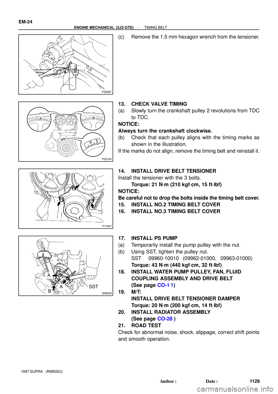
13. CHECK VALVE TIMING
(a) Slowly turn the crankshaft pulley 2 revolutions from TDC
to TDC.
NOTICE:
Always turn the crankshaft clockwise.
(b) Check that each pulley aligns with the timing marks as
shown in the illustration.
If the marks do not align, remove the timing belt and reinstall it.
14. INSTALL DRIVE BELT TENSIONER
Install the tensioner with the 3 bolts.
Torque: 21 N´m (210 kgf´cm, 15 ft´lbf)
NOTICE:
Be careful not to drop the bolts inside the timing belt cover.
15. INSTALL NO.2 TIMING BELT COVER
16. INSTALL NO.3 TIMING BELT COVER
17. INSTALL PS PUMP
(a) Temporarily install the pump pulley with the nut.
(b) Using SST, tighten the pulley nut.
SST 09960-10010 (09962-01000, 09963-01000)
Torque: 43 N´m (440 kgf´cm, 32 ft´lbf)
18. INSTALL WATER PUMP PULLEY, FAN, FLUID
COUPLING ASSEMBLY AND DRIVE BELT
(See page CO-1 1)
19. M/T:
INSTALL DRIVE BELT TENSIONER DAMPER
Torque: 20 N´m (200 kgf´cm, 14 ft´lbf)
20. INSTALL RADIATOR ASSEMBLY
(See page CO-28)
21. ROAD TEST
Check for abnormal noise, shock, slippage, correct shift points
and smooth operation.