Page 1369 of 1807

P12279
P12303
Oil Pressure
Switch
SST
P12301
Oil Pressure Gauge LU-2
- LUBRICATIONOIL AND FILTER
1449 Author�: Date�:
1997 SUPRA (RM502U)
7. DISCONNECT A/C COMPRESSOR FROM ENGINE
(a) Remove the 4 bolts and nut.
(b) Using a torx socket (E10), remove the stud bolt.
(c) Disconnect the compressor connector.
(d) Remove 4 bolts and pull the compressor downward.
8. REMOVE OIL PRESSURE SWITCH, AND INSTALL OIL
PRESSURE GAUGE
(a) Disconnect the oil pressure switch connector.
(b) Using SST, remove the oil pressure switch.
SST 09816-30010
(c) Install an oil pressure gauge.
9. REINSTALL A/C COMPRESSOR
(a) Temporarily install the A/C compressor with the 4 bolts.
(b) Connect the compressor connector.
(c) Install the compressor with the stud bolts, 4 bolts and nut.
Torque:
Stud bolt: 26 N´m (265 kgf´cm, 19 ft´lbf)
Bolt and nut: 52 N´m (530 kgf´cm, 38 ft´lbf)
10. REINSTALL DRIVE BELT
Install the drive belt by turning the drive belt tensioner clock-
wise.
11. WARM UP ENGINE
Allow the engine to warm up to normal operating temperature.
12. CHECK OIL PRESSURE
Oil pressure:
At idle
49 kPa (0.5 kgf/cm
2, 7.1 psi) or more
At 3,000 rpm (2JZ-GE) or 4,000 rpm (2JZ-GTE)
324 - 579 kPa
(3.3 - 5.9 kgf/cm
2, 47 - 84 psi)
13. REMOVE DRIVE BELT
14. DISCONNECT A/C COMPRESSOR FROM ENGINE
Page 1370 of 1807
S00888
Oil Pressure Switch Union Nut
Adhesive
- LUBRICATIONOIL AND FILTER
LU-3
1450 Author�: Date�:
1997 SUPRA (RM502U)
15. REMOVE OIL PRESSURE GAUGE, AND REINSTALL
OIL PRESSURE SWITCH
(a) Remove the oil pressure gauge.
(b) Tighten the union nut.
Torque: 60 N´m (600 kgf´cm, 44 ft´lbf)
(c) Apply adhesive to 2 or 3 thread of the oil pressure switch.
Adhesive:
Part No. 08833-00080, THREE BOND 1344,
LOCKTITE 242 or equivalent
(d) Using SST, install the oil pressure switch.
SST 09816-30010
Torque: 14 N´m (150 kgf´cm, 11 ft´lbf)
(e) Connect the oil pressure switch connector.
16. REINSTALL A/C COMPRESSOR
17. REINSTALL DRIVE BELT
18. START ENGINE AND CHECK FOR REAKS
19. 2JZ-GTE M/T:
INSTALL DRIVE BELT TENSIONER DAMPER
Torque: 20 N´m (200 kgf´cm, 14 ft´lbf)
20. 2JZ-GTE:
REINSTALL NO.2 AIR TUBE
21. REINSTALL ENGINE UNDER COVER
Page 1372 of 1807

P12212
P12206
Additional
3/4 Turn
Z13415
w/ Oil filter
Changew/o Oil filter
ChangeDry fill
2JZ-GE
2JZ-GTE5.2 Iiters
(5.5 US qts,
4.6 Imp. qts)
5.0 Iiters
(5.3 US qts,
4.4 Imp. qts)
4.9 Iiters
(5.2 US qts,
4.3 Imp. qts)6.5 Iiters
(6.9 US qts,
5.7 Imp. qts)
4.7 Iiters
(5.0 US qts,
4.1 Imp. qts)6.5 Iiters
6.9 US qts,
5.7 Imp. qts)
- LUBRICATIONOIL AND FILTER
LU-5
1452 Author�: Date�:
1997 SUPRA (RM502U)
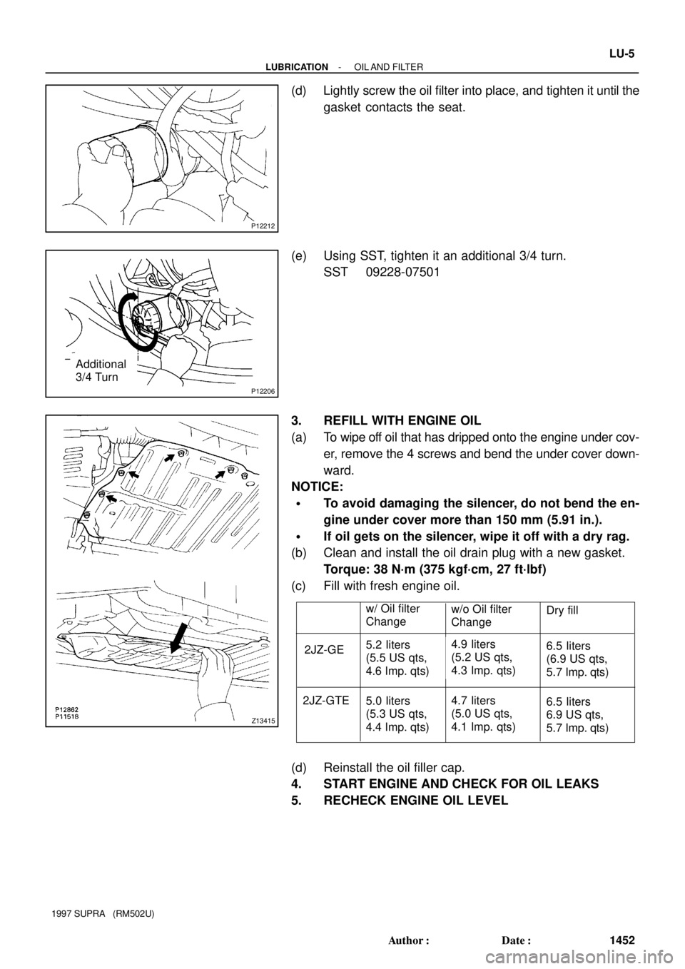
(d) Lightly screw the oil filter into place, and tighten it until the
gasket contacts the seat.
(e) Using SST, tighten it an additional 3/4 turn.
SST 09228-07501
3. REFILL WITH ENGINE OIL
(a) To wipe off oil that has dripped onto the engine under cov-
er, remove the 4 screws and bend the under cover down-
ward.
NOTICE:
�To avoid damaging the silencer, do not bend the en-
gine under cover more than 150 mm (5.91 in.).
�If oil gets on the silencer, wipe it off with a dry rag.
(b) Clean and install the oil drain plug with a new gasket.
Torque: 38 N´m (375 kgf´cm, 27 ft´lbf)
(c) Fill with fresh engine oil.
(d) Reinstall the oil filler cap.
4. START ENGINE AND CHECK FOR OIL LEAKS
5. RECHECK ENGINE OIL LEVEL
Page 1379 of 1807
LU0K1-01
P02148
P02443
P02186
Mark
ºº LU-12
- LUBRICATIONOIL PUMP
1459 Author�: Date�:
1997 SUPRA (RM502U)
DISASSEMBLY
1. REMOVE RELIEF VALVE
(a) Slightly mount the pump body in a vise.
NOTICE:
Be careful not to damage the pump body.
(b) Remove the plug, gasket (2JZ-GE), O-ring (2JZ-GTE),
compression spring and relief valve.
HINT:
At the time of reassembly, please refer to the following items.
Use a new gasket (2JZ-GE) or O-ring (2JZ-GTE).
Torque:
2JZ-GE: 49 N´m (500 kgf´cm, 36 ft´lbf)
2JZ-GTE: 29 N´m (300 kgf´cm, 22 ft´lbf)
2. REMOVE DRIVE AND DRIVEN ROTORS
Remove the 10 screws, pump body cover, the drive and driven
rotors.
Torque: 10 N´m (105 kgf´cm, 8.0 ft´lbf)
HINT:
At the time of reassembly, please refer to the following item.
Place the drive and driven rotors into the oil pump body with the
mark facing upward.
Page 1382 of 1807

LU050-02
Z02385
A
Seal WidthB
AB
2 - 3 mm
P03946
New
O-Ring
P03936
Long
Bolt LU-16
- LUBRICATIONOIL PUMP
1463 Author�: Date�:
1997 SUPRA (RM502U)
INSTALLATION
1. INSTALL OIL PUMP
(a) Remove any old packing (FIPG) material and be
careful not to drop any oil on the contact surfaces of the
oil pump and cylinder block.
�Using a razor blade gasket scraper, remove all the
old packing (FIPG) material from the gasket
surfaces and sealing groove.
�Thoroughly clean all components to remove all the
debris.
�Using a non-residue solvent, clean both sealing
surfaces.
(b) Apply seal packing to the oil pump as shown in the illustra-
tion.
Seal packing:
Part No. 08826-00080 or equivalent
�Install a nozzle that has been cut to a 2 - 3 mm (0.08
- 0.12 in.) opening.
HINT:
Avoid applying an excessive amount to the surface. Be particu-
larly careful near oil passages.
�Parts must be assembled within 5 minutes of ap-
plication. Otherwise the material must be removed
and reapplied.
�Immediately remove nozzle from the tube and rein-
stall cap.
(c) Place 2 new O-rings in position on the cylinder block.
(d) Install the oil pump with the 9 bolts.
Torque: 21 N´m (210 kgf´cm, 15 ft´lbf)
2. INSTALL NO.1 OIL PAN
(a) Remove any old packing (FIPG) material and be careful
not to drop any oil on the contact surfaces of the No.1 oil
pan and cylinder block.
�Using a razor blade and gasket scraper, remove all
the old packing (FIPG) material from the gasket sur-
faces and sealing groove.
�Thoroughly clean all components to remove all the
debris.
�Using a non-residue solvent, clean both sealing
surfaces.
NOTICE:
Do not use a solvent which will affect the painted surfaces.
Page 1383 of 1807

Z17256
Seal Width AB
4 - 5 mmC
P03949
New O-Ring
- LUBRICATIONOIL PUMP
LU-17
1464 Author�: Date�:
1997 SUPRA (RM502U)
(b) Apply seal packing to the No.1 oil pan as shown in the il-
lustration.
Seal packing:
Parts No. 08826-00080 or equivalent
�Install a nozzle that has been cut to a 4 - 5 mm (0.16
- 0.20 in.) opening.
HINT:
Avoid applying an excessive amount to the surface.
�Parts must be assembled within 5 minutes of ap-
plication. Otherwise the material must be removed
and reapplied.
�Immediately remove nozzle from the tube and rein-
stall cap.
(c) Place a new O-ring in the position on the cylinder block.
(d) Install the No.1 oil pan with the 22 bolts.
Torque:
12 mm head
21 N´m (210 kgf´cm, 15 ft´lbf)
14 mm head
39 N´m (400 kgf´cm, 29 ft´lbf)
3. 2JZ-GTE
INSTALL TURBO OIL OUTLET PIPE
(a) Install a new gasket and the oil outlet pipe with the 2 nuts.
Torque: 27 N´m (280 kgf´cm, 20 ft´lbf)
(b) Connect the 2 turbo oil outlet hoses.
4. INSTALL OIL PAN BAFFLE PLATE
Torque: 8.8 N´m (90 kgf´cm, 78 in.´lbf)
5. INSTALL OIL STRAINER
Install a new gasket and the oil strainer with the bolt and 2 nuts.
Torque: 8.8 N´m (90 kgf´cm, 78 in.´lbf)
6. INSTALL NO.2 OIL PAN
(a) Remove any old packing (FIPG) material and be
careful not to drop any oil on the contact surfaces of the
No.1 and No.2 oil pans.
�Using a razor blade and gasket scraper, remove all
the old packing (FIPG) material from the gasket sur-
faces and sealing groove.
�Thoroughly clean all components to remove all the
debris.
�Using a non-residue solvent, clean both sealing
surfaces.
NOTICE:
Do not use a solvent which will affect the painted surfaces.
Page 1384 of 1807

Z17257
Seal WidthAB
4 - 5 mmA
B
P02404
New Gasket LU-18
- LUBRICATIONOIL PUMP
1465 Author�: Date�:
1997 SUPRA (RM502U)
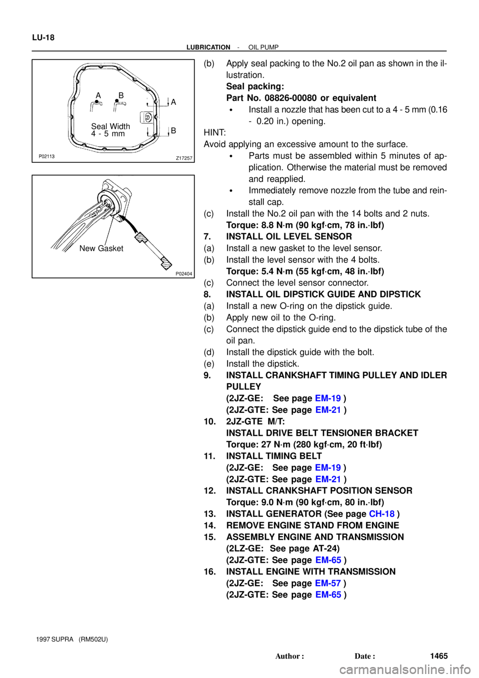
(b) Apply seal packing to the No.2 oil pan as shown in the il-
lustration.
Seal packing:
Part No. 08826-00080 or equivalent
�Install a nozzle that has been cut to a 4 - 5 mm (0.16
- 0.20 in.) opening.
HINT:
Avoid applying an excessive amount to the surface.
�Parts must be assembled within 5 minutes of ap-
plication. Otherwise the material must be removed
and reapplied.
�Immediately remove nozzle from the tube and rein-
stall cap.
(c) Install the No.2 oil pan with the 14 bolts and 2 nuts.
Torque: 8.8 N´m (90 kgf´cm, 78 in.´lbf)
7. INSTALL OIL LEVEL SENSOR
(a) Install a new gasket to the level sensor.
(b) Install the level sensor with the 4 bolts.
Torque: 5.4 N´m (55 kgf´cm, 48 in.´lbf)
(c) Connect the level sensor connector.
8. INSTALL OIL DIPSTICK GUIDE AND DIPSTICK
(a) Install a new O-ring on the dipstick guide.
(b) Apply new oil to the O-ring.
(c) Connect the dipstick guide end to the dipstick tube of the
oil pan.
(d) Install the dipstick guide with the bolt.
(e) Install the dipstick.
9. INSTALL CRANKSHAFT TIMING PULLEY AND IDLER
PULLEY
(2JZ-GE: See page EM-19)
(2JZ-GTE: See page EM-21)
10. 2JZ-GTE M/T:
INSTALL DRIVE BELT TENSIONER BRACKET
Torque: 27 N´m (280 kgf´cm, 20 ft´lbf)
11. INSTALL TIMING BELT
(2JZ-GE: See page EM-19)
(2JZ-GTE: See page EM-21)
12. INSTALL CRANKSHAFT POSITION SENSOR
Torque: 9.0 N´m (90 kgf´cm, 80 in.´lbf)
13. INSTALL GENERATOR (See page CH-18)
14. REMOVE ENGINE STAND FROM ENGINE
15. ASSEMBLY ENGINE AND TRANSMISSION
(2LZ-GE: See page AT-24)
(2JZ-GTE: See page EM-65)
16. INSTALL ENGINE WITH TRANSMISSION
(2JZ-GE: See page EM-57)
(2JZ-GTE: See page EM-65)
Page 1388 of 1807
LU04T-02
P11208
New O-Ring LU-22
- LUBRICATIONOIL COOLER (2JZ-GTE)
1469 Author�: Date�:
1997 SUPRA (RM502U)
INSTALLATION
1. INSTALL OIL COOLER
(a) Install 2 new O-rings to the oil cooler.
(b) Apply a light coat of engine oil on the threads and under
the head of the relief valve.
(c) Temporarily install the oil cooler with the plate washer and
relief valve.
(d) Tighten the relief valve.
Torque: 78 N´m (800 kgf´cm, 58 ft´lbf)
2. CONNECT WATER BYPASS HOSES TO OIL
COOLER
3. CONNECT PS OIL RESERVOIR
4. INSTALL OIL FILTER
5. FILL WITH ENGINE COOLANT
6. START ENGINE AND CHECK FOR LEAKS
7. CHECK ENGINE OIL LEVEL