Page 1459 of 1807

RS073-02
RS-36
- SUPPLEMENTAL RESTRAINT SYSTEMAIRBAG SENSOR ASSEMBLY
1975 Author�: Date�:
1997 SUPRA (RM502U)
INSTALLATION
NOTICE:
�Never use SRS parts from another vehicle. When re-
placing parts, replace them with new parts.
�Never reuse the airbag sensor assembly involved in
a collision when the airbag has deployed.
�Never repair a sensor in order to reuse it.
1. INSTALL AIRBAG SENSOR ASSEMBLY
(a) Using a torx wrench, install the airbag sensor assembly
with 4 screws.
Torx wrench: T40 (Part No.09042-00020 or locally
manufactured tool)
Torque: 21 N´m (210 kgf´cm, 15 ft´lbf)
(b) Connect the airbag sensor connectors.
NOTICE:
�Installation of the connector is done after the sensor
assembly has been installed.
�Make sure the sensor assembly is installed with the
specified torque.
�If the sensor assembly has been dropped, or there are
cracks, dents or other defects in the case, bracket or
connector, replace the sensor assembly with a new
one.
�When installing the senor assembly, take care that
the SRS wiring does not interfere with other parts and
is not pinched between other parts.
�After installing , shake the sensor assembly to check
that there is no looseness.
2. INSTALL THESE PARTS:
(a) Console box
(b) Parking brake hole cover
(c) Console panel upper
Page 1463 of 1807

P12822
Plug
P12089
New
Gasket
FI1654
Fulcrum Length
30 cm
SST
P11303
New
O-Ring
New
Insulator
P12837
Delivery Pipe
O-Ring
Insulator
Intake
ManifoldInjector
Holder
Injector
SpacerInsulator
- SFI (2JZ-GTE)SFI SYSTEM
SF-3
1329 Author�: Date�:
1997 SUPRA (RM502U)
(3) Put a container under the connection.
(4) Slowly loosen the connection.
(5) Disconnect the connection.
(6) Plug the connection with a rubber plug.
(7) Reconnect the fuel pump connector.
(b) When connecting the flare nut or union bolt on the high
pressure pipe union, observe the following procedures:
(1) Union Bolt Type:
Always use a new gasket.
(2) Union Bolt Type:
Tighten the union bolt by hand.
(3) Union Bolt Type:
Tighten the union bolt to the specified torque.
Torque: 29 N´m (300 kgf´cm, 22 ft´lbf)
(4) Flare Nut Type:
Apply a light coat of engine oil to the flare nut and
tighten the flare nut by hand.
(5) Flare Nut Type:
Using SST, tighten the flare nut to the specified
torque.
SST 09631-22020
Torque: 30 N´m (310 kgf´cm, 22 ft´lbf)
HINT:
Use a torque wrench with a fulcrum length of 30 cm (11.81 in.).
(c) Observe the following precautions when removing and
installing the injectors.
(1) Never reuse the O-ring.
(2) When placing a new O-ring on the injector, take
care not to damage it in any way.
(3) Coat a new O-ring with spindle oil or gasoline be-
fore installing-never use engine, gear or brake oil.
(d) Install the injector to the delivery pipe and intake manifold
as shown in the illustration.
Page 1465 of 1807

Q08242
TOYOTA Hand-Held Tester
DLC3
P11446Fuel Inlet Hose
P12558
Fuel Inlet
Hose
SF0GH-01
Z13307
Fuel Inlet HoseSST
Gasket
SSTSST
Gasket(Union)
- SFI (2JZ-GTE)FUEL PUMP
SF-5
1331 Author�: Date�:
1997 SUPRA (RM502U)
FUEL PUMP
ON-VEHICLE INSPECTION
1. CHECK FUEL PUMP OPERATION
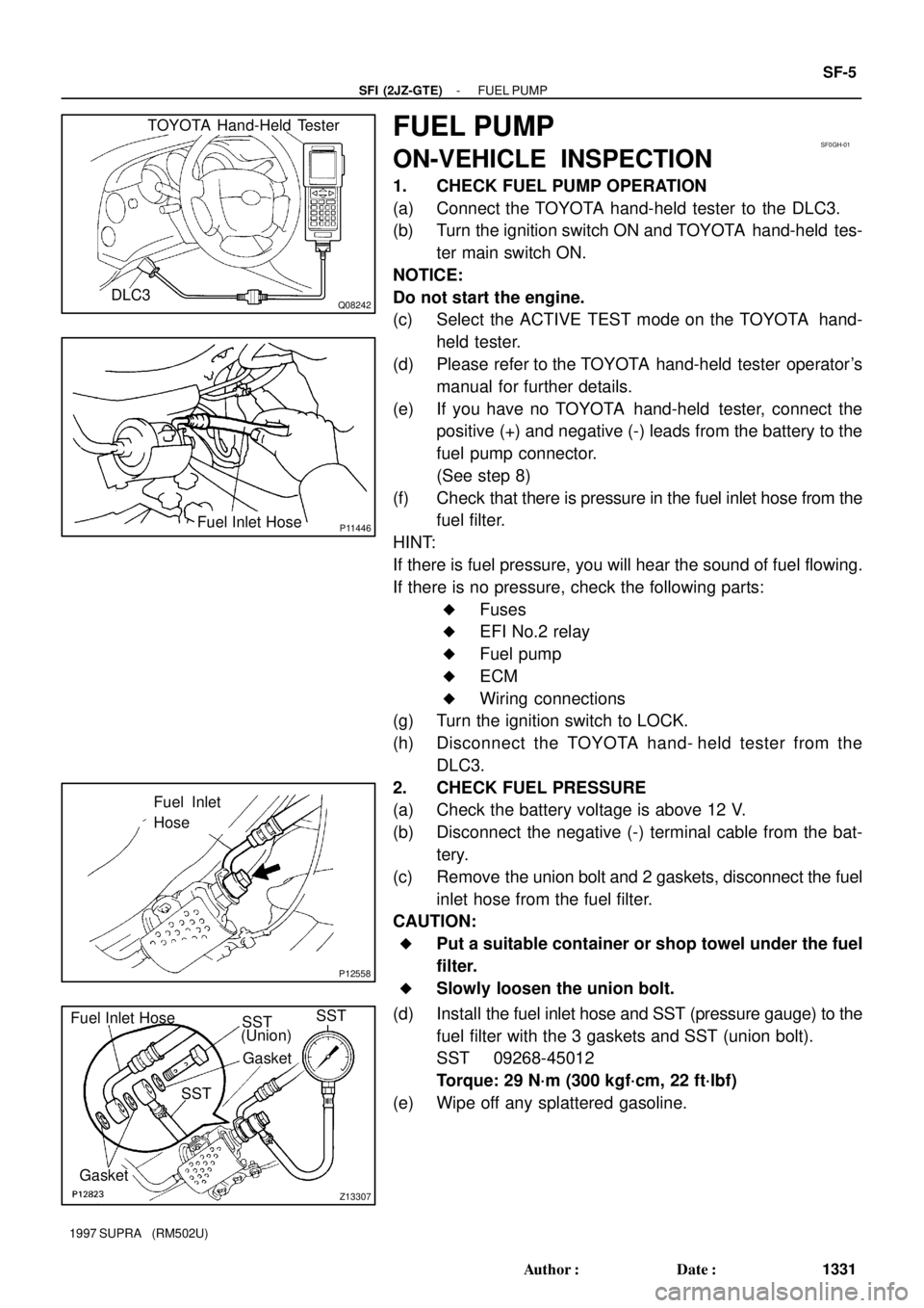
(a) Connect the TOYOTA hand-held tester to the DLC3.
(b) Turn the ignition switch ON and TOYOTA hand-held tes-
ter main switch ON.
NOTICE:
Do not start the engine.
(c) Select the ACTIVE TEST mode on the TOYOTA hand-
held tester.
(d) Please refer to the TOYOTA hand-held tester operator's
manual for further details.
(e) If you have no TOYOTA hand-held tester, connect the
positive (+) and negative (-) leads from the battery to the
fuel pump connector.
(See step 8)
(f) Check that there is pressure in the fuel inlet hose from the
fuel filter.
HINT:
If there is fuel pressure, you will hear the sound of fuel flowing.
If there is no pressure, check the following parts:
�Fuses
�EFI No.2 relay
�Fuel pump
�ECM
�Wiring connections
(g) Turn the ignition switch to LOCK.
(h) Disconnect the TOYOTA hand- held tester from the
DLC3.
2. CHECK FUEL PRESSURE
(a) Check the battery voltage is above 12 V.
(b) Disconnect the negative (-) terminal cable from the bat-
tery.
(c) Remove the union bolt and 2 gaskets, disconnect the fuel
inlet hose from the fuel filter.
CAUTION:
�Put a suitable container or shop towel under the fuel
filter.
�Slowly loosen the union bolt.
(d) Install the fuel inlet hose and SST (pressure gauge) to the
fuel filter with the 3 gaskets and SST (union bolt).
SST 09268-45012
Torque: 29 N´m (300 kgf´cm, 22 ft´lbf)
(e) Wipe off any splattered gasoline.
Page 1466 of 1807

Q08242
TOYOTA Hand-Held Tester
DLC3
P12563
Disconnect
Plug SF-6
- SFI (2JZ-GTE)FUEL PUMP
1332 Author�: Date�:
1997 SUPRA (RM502U)
(f) Connect the TOYOTA hand-held tester to the DLC3.
(See step 1 in check fuel pump operation (a) to (e).)
(g) Reconnect the negative (-) terminal cable to the battery.
(h) Turn the ignition switch ON.
(i) Measure the fuel pressure.
Fuel pressure:
226 - 275 kPa (2.3 - 2.8 kgf/cm
2, 33 - 40 psi)
If pressure is high, replace the fuel pressure regulator.
If pressure is low, check the following parts:
(1) Fuel hoses and connections
(2) Fuel pump
(3) Fuel filter
(4) Fuel pressure regulator
(j) Remove the TOYOTA hand-held tester from the
DLC3.
(k) Start the engine.
(l) Disconnect the vacuum sensing hose from the fuel pres-
sure regulator, and plug the hose end.
(m) Measure the fuel pressure at idle.
Fuel pressure:
226 - 275 kPa (2.3 - 2.8 kgf/cm
2, 33 - 40 psi)
(n) Reconnect the vacuum sensing hose to the fuel pressure
regulator.
(o) Measure the fuel pressure at idle.
Fuel pressure:
167 - 216 kPa (1.7 - 2.2 kgf/cm
2, 24 - 31 psi)
If pressure is not as specified, check the vacuum sensing hose
and fuel pressure regulator.
(p) Stop the engine.
(q) Check that the fuel pressure remains as specified for 5
minutes after the engine has stopped.
Fuel pressure:
147 kPa (1.5 kgf/cm
2, 21 psi) or more
If pressure is not as specified, check the fuel pump, pressure
regulator and/or injectors.
(r) After checking fuel pressure, disconnect the negative (-)
terminal cable from the battery and carefully remove the
SST to prevent gasoline from splashing.
SST 09268-45012
(s) Reinstall the fuel inlet hose to the fuel filter with 2 new gas-
kets and the union bolt.
Torque: 29 N´m (300 kgf´cm, 22 ft´lbf)
(t) Reconnect the negative (-) terminal cable to the battery.
(u) Check for fuel leaks.
3. TAKE OUT FLOOR CARPET
4. REMOVE SPARE WHEEL COVER
5. REMOVE SPARE WHEEL
6. REMOVE SERVICE HOLE COVER
7. DISCONNECT FUEL PUMP & SENDER GAUGE CON-
NECTOR
Page 1472 of 1807
SF0GM-01
P12033
Fuel Return
Hose
P13168
Z09524
SST
Rib
Area
P11279
- SFI (2JZ-GTE)FUEL PUMP
SF-13
1339 Author�: Date�:
1997 SUPRA (RM502U)
INSTALLATION
1. INSTALL FUEL PUMP AND SENDER GAUGE
ASSEMBLY
(a) Install a new gasket to the fuel tank.
(b) Insert fuel pump and sender gauge assembly into the fuel
tank.
(c) Connect the fuel return hose to the return port of the fuel
pump bracket.
(d) Align the arrow marks of the fuel pump bracket and fuel
tank.
(e) Temporarily install the retainer.
(f) Using SST, tighten the retainer until the arrow mark on the
retainer is within the lines on the fuel tank.
SST 09808-14010
(g) Check that the arrow marks of the fuel pump bracket and
fuel tank are aligned.
(h) Install the retainer clamp.
(i) Connect the connector and hoses to the fuel pump brack-
et:
�Fuel pump connector
�Fuel outlet hose
Connect the outlet hose with 2 new gaskets and the
union bolt.
Torque: 29 N´m (300 kgf´cm, 22 ft´lbf)
Page 1476 of 1807
SF0GP-01
B02654
New O-Ring
P13049
Pressure
Regulator
New
O - Ring
Delivery
Pipe
CORRECT WRONGWRONG
P11324
- SFI (2JZ-GTE)FUEL PRESSURE REGULATOR
SF-17
1343 Author�: Date�:
1997 SUPRA (RM502U)
INSTALLATION
1. INSTALL FUEL PRESSURE REGULATOR
(a) Apply a light coat of gasoline to a new O-ring, and install
it to the pressure regulator.
(b) Attach the pressure regulator to the delivery pipe.
(c) Check that the pressure regulator rotates smoothly.
NOTICE:
If it does not rotate smoothly, the O-ring may be pinched,
so remove the pressure regulator and do steps (b) and (c)
above again.
(d) Install the pressure regulator with the 2 bolts.
Torque: 9.0 N´m (90 kgf´cm, 80 in.´lbf)
2. CONNECT FUEL RETURN PIPE TO FUEL PRESSURE
REGULATOR
Install the return pipe with 2 new gaskets and the union bolt.
Torque: 28 N´m (280 kgf´cm, 21 ft´lbf)
3. CONNECT VACUUM SENSING HOSE TO FUEL
PRESSURE REGULATOR
4. INSTALL THROTTLE BODY
(See page SF-48)
5. CHECK FOR FUEL LEAKS
(See page SF-1)
Page 1479 of 1807

SF0GS-02
P12565
Pull
O-Ring
S00910
Engine Wire Clamp
O-Ring
Pull
Fuel
Return
Hose
P11322
Chamber
StagCable
Bracket
P11321(1) (2) (3)(4) SF-20
- SFI (2JZ-GTE)INJECTOR
1346 Author�: Date�:
1997 SUPRA (RM502U)
REMOVAL
1. REMOVE ENGINE UNDER COVER
2. REMOVE THROTTLE BODY
(See page SF-43)
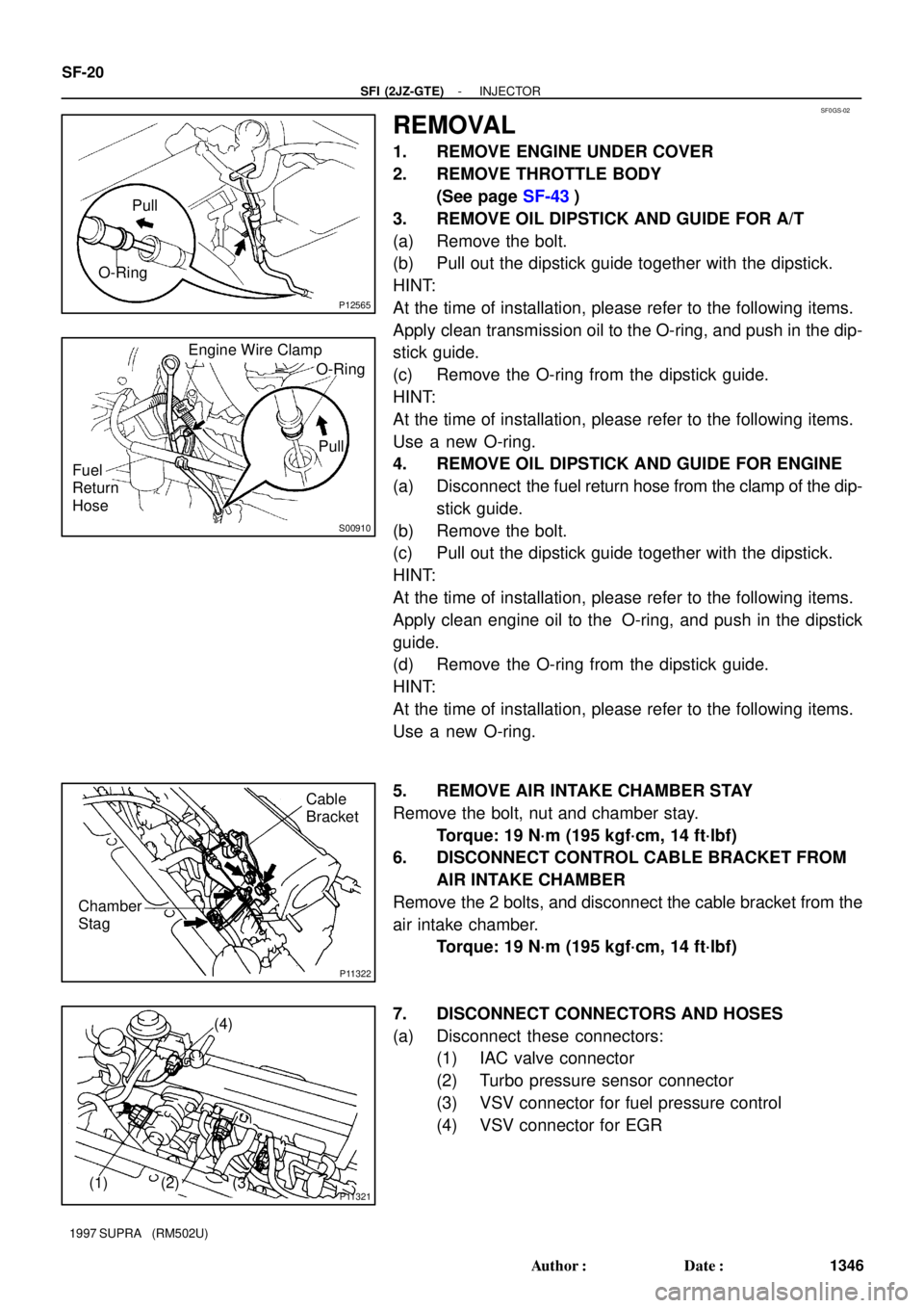
3. REMOVE OIL DIPSTICK AND GUIDE FOR A/T
(a) Remove the bolt.
(b) Pull out the dipstick guide together with the dipstick.
HINT:
At the time of installation, please refer to the following items.
Apply clean transmission oil to the O-ring, and push in the dip-
stick guide.
(c) Remove the O-ring from the dipstick guide.
HINT:
At the time of installation, please refer to the following items.
Use a new O-ring.
4. REMOVE OIL DIPSTICK AND GUIDE FOR ENGINE
(a) Disconnect the fuel return hose from the clamp of the dip-
stick guide.
(b) Remove the bolt.
(c) Pull out the dipstick guide together with the dipstick.
HINT:
At the time of installation, please refer to the following items.
Apply clean engine oil to the O-ring, and push in the dipstick
guide.
(d) Remove the O-ring from the dipstick guide.
HINT:
At the time of installation, please refer to the following items.
Use a new O-ring.
5. REMOVE AIR INTAKE CHAMBER STAY
Remove the bolt, nut and chamber stay.
Torque: 19 N´m (195 kgf´cm, 14 ft´lbf)
6. DISCONNECT CONTROL CABLE BRACKET FROM
AIR INTAKE CHAMBER
Remove the 2 bolts, and disconnect the cable bracket from the
air intake chamber.
Torque: 19 N´m (195 kgf´cm, 14 ft´lbf)
7. DISCONNECT CONNECTORS AND HOSES
(a) Disconnect these connectors:
(1) IAC valve connector
(2) Turbo pressure sensor connector
(3) VSV connector for fuel pressure control
(4) VSV connector for EGR
Page 1480 of 1807

P11991
P11317
(1)
(2)
(3) Clamp
P11318(4)
(5)
S04464
(10)
(8)
(6)(7)(9) (11)
S04463
EGR Gas
Temperature
Sensor
Connector
EGR Pipe
- SFI (2JZ-GTE)INJECTOR
SF-21
1347 Author�: Date�:
1997 SUPRA (RM502U)
(b) Remove the bolt, and disconnect the engine wire protec-
tor from the body.
(c) Disconnect these hoses:
(1) Air hose from IAC valve
Disconnect the IAC valve pipe from the clamp on
the cylinder head cover, and disconnect the air hose
from the IAC valve.
(2) Air hose (from air intake chamber) from
vacuum pipe on IAC valve pipe
(3) Air hose for EGR from valve pipe
(4) PCV hose from PCV valve
(5) Vacuum sensing hose from fuel pressure
regulator
(6) Water bypass hose (from IAC valve) from No.4 wa-
ter bypass pipe
(7) EVAP hose (from air intake chamber) from
vacuum pipe on manifold stay
(8) EVAP hose (from vacuum pipe on No.4 water
bypass pipe) from No.2 vacuum pipe
(9) EVAP hose (from charcoal canister) from No.2
vacuum pipe
(10) PS air hose from air intake chamber
(11) Brake booster vacuum hose from union on air in-
take chamber
8. DISCONNECT EGR GAS TEMPERATURE SENSOR
CONNECTOR
(a) Disconnect the connector from the No.2 vacuum pipe.
(b) Disconnect the sensor connector from the wiring connec-
tor.
9. REMOVE EGR PIPE
(a) Remove the union bolt holding the EGR pipe to the EGR
valve.
Torque: 64 N´m (650 kgf´cm, 47 ft´lbf)