Page 1481 of 1807

P11315
No.4 Water
Bypass Pipe
Manifold Stay
P11314
Clamp
Ground
Cable
S04462
P11312
Water
Hose Bypass
Z09317(3) GrayDark
(1)(2)
Gray
(1)Gray
(1)Dark
Gray
(1)(2)
Gray
(1)
Dark
Gray
(1) SF-22
- SFI (2JZ-GTE)INJECTOR
1348 Author�: Date�:
1997 SUPRA (RM502U)
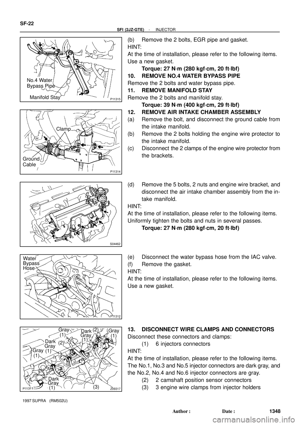
(b) Remove the 2 bolts, EGR pipe and gasket.
HINT:
At the time of installation, please refer to the following items.
Use a new gasket.
Torque: 27 N´m (280 kgf´cm, 20 ft´lbf)
10. REMOVE NO.4 WATER BYPASS PIPE
Remove the 2 bolts and water bypass pipe.
11. REMOVE MANIFOLD STAY
Remove the 2 bolts and manifold stay.
Torque: 39 N´m (400 kgf´cm, 29 ft´lbf)
12. REMOVE AIR INTAKE CHAMBER ASSEMBLY
(a) Remove the bolt, and disconnect the ground cable from
the intake manifold.
(b) Remove the 2 bolts holding the engine wire protector to
the intake manifold.
(c) Disconnect the 2 clamps of the engine wire protector from
the brackets.
(d) Remove the 5 bolts, 2 nuts and engine wire bracket, and
disconnect the air intake chamber assembly from the in-
take manifold.
HINT:
At the time of installation, please refer to the following items.
Uniformly tighten the bolts and nuts in several passes.
Torque: 27 N´m (280 kgf´cm, 20 ft´lbf)
(e) Disconnect the water bypass hose from the IAC valve.
(f) Remove the gasket.
HINT:
At the time of installation, please refer to the following items.
Use a new gasket.
13. DISCONNECT WIRE CLAMPS AND CONNECTORS
Disconnect these connectors and clamps:
(1) 6 injectors connectors
HINT:
At the time of installation, please refer to the following items.
The No.1, No.3 and No.5 injector connectors are dark gray, and
the No.2, No.4 and No.6 injector connectors are gray.
(2) 2 camshaft position sensor connectors
(3) 3 engine wire clamps from injector holders
Page 1482 of 1807

P11310
Fuel
Return
PipeFuel
Inlet
Pipe
P11309
Z09319
Insulator
P11307
P11305
Spacer
- SFI (2JZ-GTE)INJECTOR
SF-23
1349 Author�: Date�:
1997 SUPRA (RM502U)
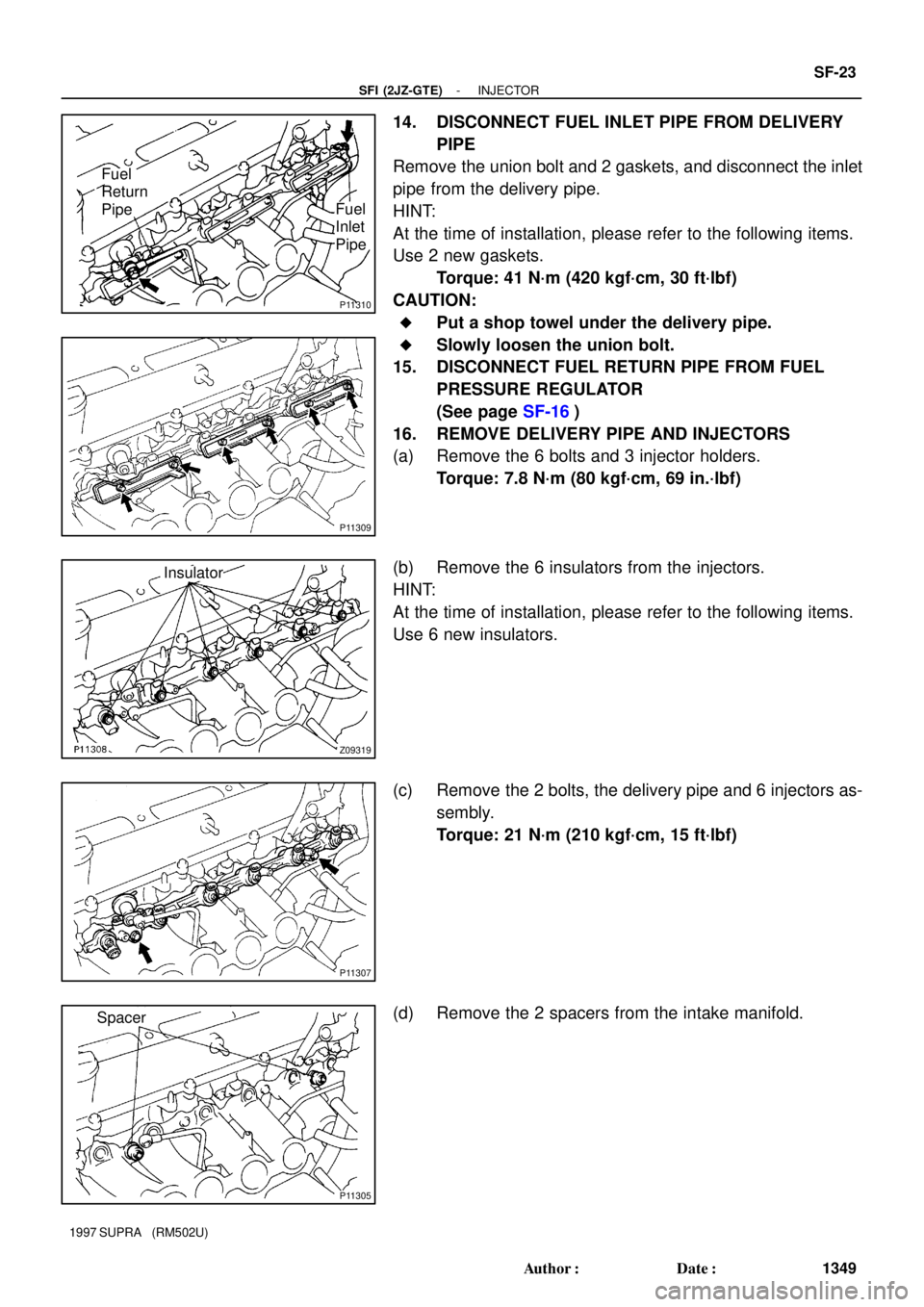
14. DISCONNECT FUEL INLET PIPE FROM DELIVERY
PIPE
Remove the union bolt and 2 gaskets, and disconnect the inlet
pipe from the delivery pipe.
HINT:
At the time of installation, please refer to the following items.
Use 2 new gaskets.
Torque: 41 N´m (420 kgf´cm, 30 ft´lbf)
CAUTION:
�Put a shop towel under the delivery pipe.
�Slowly loosen the union bolt.
15. DISCONNECT FUEL RETURN PIPE FROM FUEL
PRESSURE REGULATOR
(See page SF-16)
16. REMOVE DELIVERY PIPE AND INJECTORS
(a) Remove the 6 bolts and 3 injector holders.
Torque: 7.8 N´m (80 kgf´cm, 69 in.´lbf)
(b) Remove the 6 insulators from the injectors.
HINT:
At the time of installation, please refer to the following items.
Use 6 new insulators.
(c) Remove the 2 bolts, the delivery pipe and 6 injectors as-
sembly.
Torque: 21 N´m (210 kgf´cm, 15 ft´lbf)
(d) Remove the 2 spacers from the intake manifold.
Page 1484 of 1807
SF0GT-02
P12826
Injector
Fuel Pressure Regulator
SST
(Union)
Fuel Return Hose
(On Vehicle)SST
(Union) Fuel Filter
(On Vehicle)SST
(Hose)SST
Union Delivery Pipe
P11302
Insulator
P12558
Fuel Inlet
Hose
- SFI (2JZ-GTE)INJECTOR
SF-25
1351 Author�: Date�:
1997 SUPRA (RM502U)
INSPECTION
1. INSPECT INJECTOR INJECTION
CAUTION:
Keep injector clear of sparks during the test.
(a) Install the insulator to each injector.
(b) Install the 3 injector holders with the 6 bolts.
Torque: 7.8 N´m (80 kgf´cm, 69 in.´lbf)
(c) Remove the union bolt and 2 gaskets, and disconnect the
fuel inlet hose from the fuel filter outlet.
Page 1485 of 1807
Z13305
SST
(Union)SST
(Hose)Union
Bolt
Gasket
P12559Fuel Return Hose
Z13308
Fuel Return
Hose
SST
(Union)
Gasket
Union
Bolt
Z13304
SST (Union) Gasket
Union
Bolt
SST (Hose) SF-26
- SFI (2JZ-GTE)INJECTOR
1352 Author�: Date�:
1997 SUPRA (RM502U)
(d) Connect SST (hose) to the fuel filter outlet with SST
(union), the 2 gaskets and union bolt.
SST 09268-41046 (90405-09015)
Torque: 29 N´m (300 kgf´cm, 22 ft´lbf)
(e) Disconnect the fuel return hose from the fuel return pipe.
(f) Connect the fuel return hose to the fuel outlet of the pres-
sure regulator on the delivery pipe with SST (union), the
2 gaskets and union bolt.
SST 09268-41046 (09268-41071)
(g) Connect SST (hose) to the fuel inlet of the delivery pipe
with SST (union), the 2 gaskets and union bolt.
SST 09268-41046 (90405-09015)
(h) Put the injector into the graduated cylinder.
Page 1486 of 1807

Q08242
TOYOTA Hand-Held Tester
DLC3
P12548
SST (Wire)
Connect
P12549
- SFI (2JZ-GTE)INJECTOR
SF-27
1353 Author�: Date�:
1997 SUPRA (RM502U)
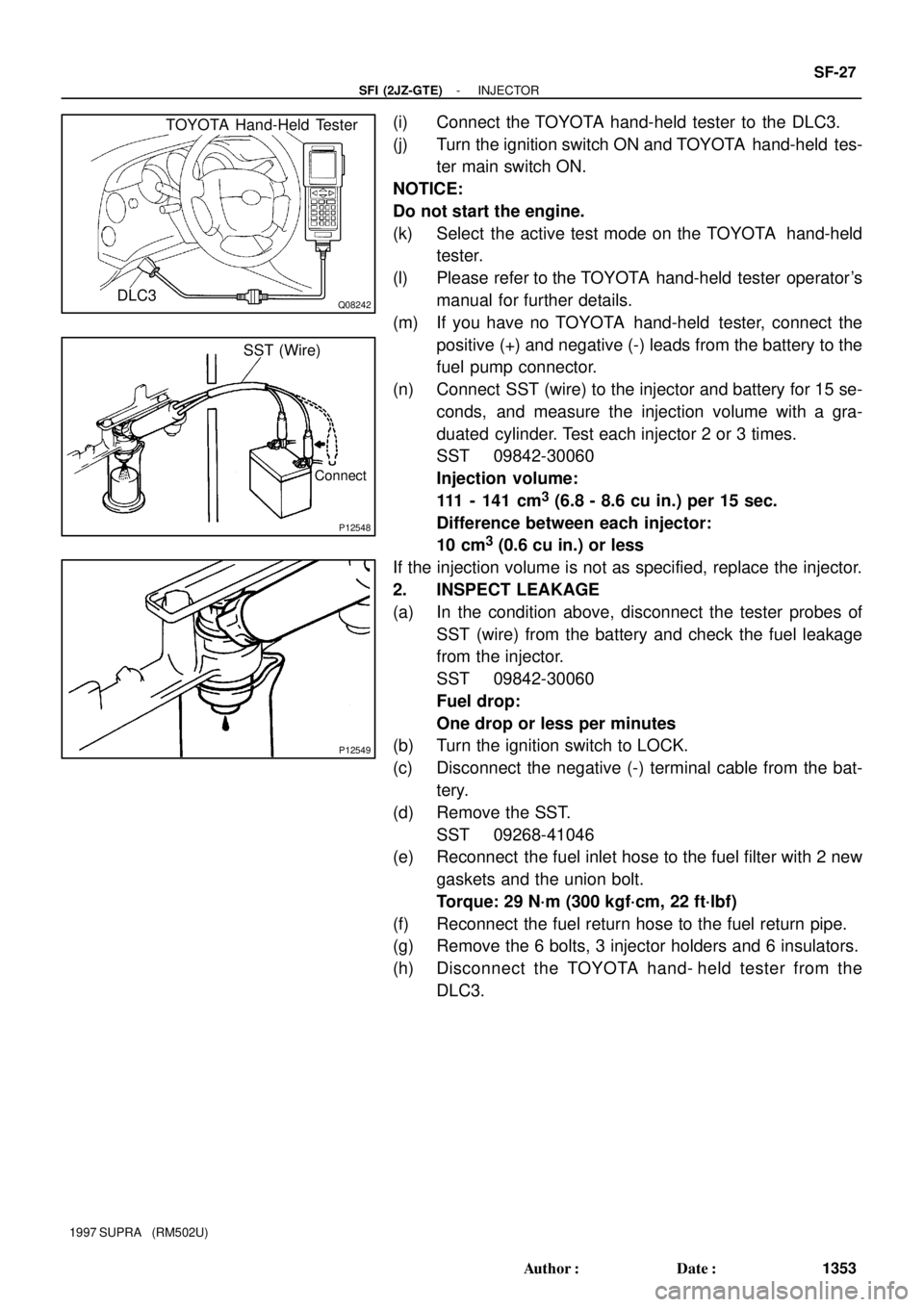
(i) Connect the TOYOTA hand-held tester to the DLC3.
(j) Turn the ignition switch ON and TOYOTA hand-held tes-
ter main switch ON.
NOTICE:
Do not start the engine.
(k) Select the active test mode on the TOYOTA hand-held
tester.
(l) Please refer to the TOYOTA hand-held tester operator's
manual for further details.
(m) If you have no TOYOTA hand-held tester, connect the
positive (+) and negative (-) leads from the battery to the
fuel pump connector.
(n) Connect SST (wire) to the injector and battery for 15 se-
conds, and measure the injection volume with a gra-
duated cylinder. Test each injector 2 or 3 times.
SST 09842-30060
Injection volume:
111 - 141 cm
3 (6.8 - 8.6 cu in.) per 15 sec.
Difference between each injector:
10 cm
3 (0.6 cu in.) or less
If the injection volume is not as specified, replace the injector.
2. INSPECT LEAKAGE
(a) In the condition above, disconnect the tester probes of
SST (wire) from the battery and check the fuel leakage
from the injector.
SST 09842-30060
Fuel drop:
One drop or less per minutes
(b) Turn the ignition switch to LOCK.
(c) Disconnect the negative (-) terminal cable from the bat-
tery.
(d) Remove the SST.
SST 09268-41046
(e) Reconnect the fuel inlet hose to the fuel filter with 2 new
gaskets and the union bolt.
Torque: 29 N´m (300 kgf´cm, 22 ft´lbf)
(f) Reconnect the fuel return hose to the fuel return pipe.
(g) Remove the 6 bolts, 3 injector holders and 6 insulators.
(h) Disconnect the TOYOTA hand- held tester from the
DLC3.
Page 1490 of 1807
SF0GY-02
B02656
New
Gasket
(Large)
New
Gasket
(Small)
B02657
Fulcrum
LengthSST SF-32
- SFI (2JZ-GTE)FUEL PRESSURE PULSATION DAMPER
1358 Author�: Date�:
1997 SUPRA (RM502U)
INSTALLATION
1. INSTALL FUEL PRESSURE PULSATION DAMPER
(a) Install the fuel inlet pipe and pulsation damper with 2 new
gaskets.
HINT:
Different sized gaskets are used for the upper (large size) and
lower (small size).
(b) Using SST, tighten the pulsation damper.
SST 09612-24014 (09617-24011)
Torque:
41 N´m (420 kgf´cm, 30 ft´lbf)
35 N´m (350 kgf´cm, 25 ft´lbf) for SST
HINT:
Use a torque wrench with a fulcrum length of 30 cm (11.81 in.).
2. INSTALL STARTER
(See page ST-15)
3. CHECK FOR FUEL LEAKS
(See page SF-1)
Page 1494 of 1807
SF0H3-01
P12084
ClampConnector
- SFI (2JZ-GTE)MASS AIR FLOW (MAF) METER
SF-37
1363 Author�: Date�:
1997 SUPRA (RM502U)
REMOVAL
1. REMOVE NO.1 AIR HOSE
2. REMOVE AIR CLEANER HOSE
3. REMOVE MAF METER
(a) Remove the 2 bolts, and disconnect the MAF meter from
the air cleaner case.
Torque: 6.9 N´m (70 kgf´cm, 61 in.´lbf)
(b) Disconnect the MAF meter wire from the wire clamp on
the air cleaner case.
(c) Disconnect the MAF meter connector, and remove the
MAF meter.
Page 1499 of 1807
P11327
(4) (3)
(2)
(!) (5)
(6)
P11328
SF0H8-01
P11329
(1)
(2)
(3)
(4)
- SFI (2JZ-GTE)THROTTLE BODY
SF-43
1369 Author�: Date�:
1997 SUPRA (RM502U)
REMOVAL
1. DRAIN ENGINE COOLANT
2. REMOVE THROTTLE BODY
(a) Disconnect the hose, cables and connectors from the
throttle body:
(1) Air hose
(2) Accelerator cable
(3) Cruise control actuator cable
(4) Throttle position sensor connector
(5) Sub-throttle position sensor connector
(6) Sub-throttle actuator connector
(b) Remove the 2 bolts and 2 nuts, and disconnect the
throttle body from the air intake chamber.
Torque: 21 N´m (210 kgf´cm, 15 ft´lbf)
(c) Remove the gasket.
HINT:
Use a new gasket.
(d) Disconnect these hoses from the throttle body, and re-
move the throttle body:
(1) EVAP hose
(2) Water bypass hose (from No.4 water bypass pipe)
(3) Water bypass hose (from cylinder head)
(4) PS air hose