Page 389 of 1807

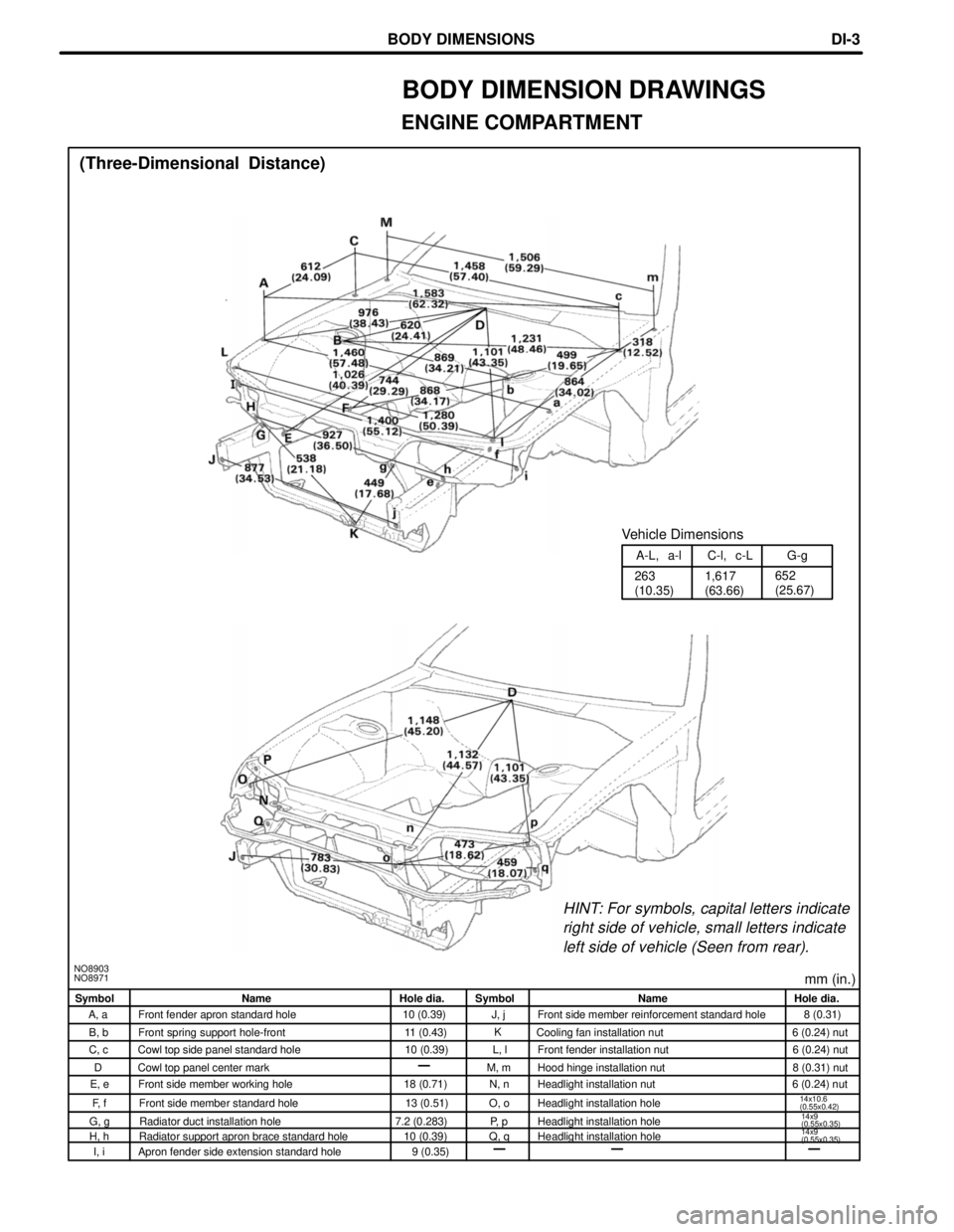
mm (in.)NO8903
NO8971
HINT: For symbols, capital letters indicate
right side of vehicle, small letters indicate
left side of vehicle (Seen from rear).
1,617
(63.66) 263
(10.35)652
(25.67) A-L, a-l C-l, c-L G-g
Vehicle Dimensions
(Three-Dimensional Distance)
Symbol Name Hole dia. Symbol Name Hole dia.
A, a Front fender apron standard hole 10 (0.39) J, j Front side member reinforcement standard hole 8 (0.31)
B, b Front spring support hole-front 11 (0.43) Cooling fan installation nut 6 (0.24) nut
C, c Cowl top side panel standard hole 10 (0.39) L, l Front fender installation nut 6 (0.24) nut
Cowl top panel center mark M, m Hood hinge installation nut 8 (0.31) nut
E, e Front side member working hole 18 (0.71) N, n Headlight installation nut 6 (0.24) nut
F, f Front side member standard hole 13 (0.51) O, o Headlight installation hole
14x10.6
(0.55x0.42)
G, g Radiator duct installation hole 7.2 (0.283) P, p Headlight installation hole
H, h Radiator support apron brace standard hole 10 (0.39) Q, q Headlight installation hole
I, i Apron fender side extension standard hole 9 (0.35)
BODY DIMENSION DRAWINGS
ENGINE COMPARTMENT
D
14x9
(0.55x0.35)
14x9
(0.55x0.35)
K
BODY DIMENSIONSDI-3
Page 407 of 1807
mm in.
4.5
4.6
5.0
6.5
9.20.177
0.181
0.197
0.256
0.362
FIT STANDARDS
After doors and the engine hood are installed, be sure to perform fit adjustment to prevent abnormal wind
noise and ensure a good appearance.
5.0 mm
4.5 mm
4.5 mm
4.6 mm
9.2 mm
6.5 mm
5.0 mm
APPENDIXAP-2
Page 445 of 1807
Roof Side Inner Garnish (PP)
Rear Speaker Grille (ABS/PET)
Quarter Inside Trim Board (PP)
Front Pillar Garnish (PP)
Cowl Side Trim (PP/PE)
Radiator Upper Air
Deflector (PP/PE)
Front Door Scuff Outside Plate (PP)
Front Fender Liner (PE) Radiator
Reserver Tank (PP)
Windshield Washer Jar (PP)
Front Fender splash shield (PE)
Engine Under No. 1 Cover (PP/PE)Engine Under No. 4 Cover (PE)
Engine Under No. 2 Cover (PE)
HINT:
wResin material differs with model.
/ Made up of 2 or more kinds of materials.
PLASTIC BODY PARTSPP-5
Page 507 of 1807

PRICES SUBJECT TO CHANGE WITHOUT NOTICEORDERING INFORMATION ON PAGE 5
TOYOTA COLLISION REPAIR & REFINISH PAGE 4 of 5
SERVICE PUBLICATIONS (cont'd)
COLLISION REPAIR INFORMATION BULLETINS
Collision Repair Information Bulletins (CRIBS) provide Toyota body and paint technicians
with the latest developments in collision repair and refinish. Information is divided among
the following topics:
�General information�Interior
�Structural repair�Electrical
�Welding�Alignment
�Refinish�Tools and equipment
�Exterior
Name
Part NumberPrice
Collision Repair Information Binder
includes Bulletins #1±41 00408±03000±01 $20.00
CRIB Bulletin #49 00408±03000±49 1.00
CRIB Bulletins #51±57 00408±03000±51±57 10.00
CRIB Bulletins #58±61 00408±03000±58±61 5.00
CRIB Bulletins #62±65 00408±03000±62±65 5.00
CRIB Bulletins #66±67 00408±03000±66±67 5.00
CRIB Bulletins #68±69 00408±03000±68±69 1.18
CRIB Bulletin #70 00408±03000±70 2.00
CRIB Bulletin #71 00408±03000±71 2.24
CRIB Bulletin #72 00408±03000±72 1.62
BODY DIMENSIONS GUIDE
The Toyota Body Dimension Guide provides data necessary to assess the extent of
collision damage by using vehicle±specific dimension charts and measurement
specifications. The dimension guide provides specifications for the following areas:
�engine compartment�suspension crossmember
�door and compartment openings�frame alignment
�underbody�cab alignment
1980±1997 Body Dimension Guide 00117±00540±97 $3.50
Page 509 of 1807
NO8908
(Three-Dimensional Distance)
Imaginary
Standard
Line
mm (in.)
Hole dia.
10 (0.39)
18 (0.71)
14 (0.55)nut
10 (0.39)nut
18 (0.71)
10 (0.39)nut
12 (0. 47)nut Name
Front floor reinforcement standard hole
Rear floor side member standard hole
Rear suspension member installation nut
Suspension member bracket installation nut-front, outer
Rear floor side member rear standard hole
Tank band installation nut
Transport hook installation nut Symbol
L, l
M, m
N, n
P, p
Q, q
R Hole dia.
7 (0.28)
9 (0.35)
18 (0.71)
13 (0.51)
14 (0.55) nut
18 (0.71)
10 (0.39) nut
10(0.39) nut Name
Font side member standard hole
Font crossmember working hole
Font side member standard hole
Font suspension crossmember installation hole
Front suspension crossmember installation nut
Front side member standard hole
Engine rear mounting member installation nut-front
Propeller shaft center support bearing installation nut Symbol
A, a
B, b
D, d
F, f
H, h
I, i
J, j
K, k
UNDER BODY
r
BODY DIMENSIONSDI-8
Page 510 of 1807

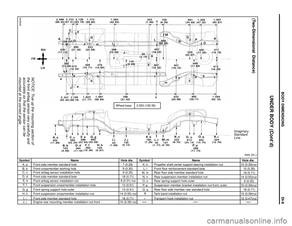
NOTICE: True up the mounting section of
the front airbag sensor very carefully and
accurately so that the sensor can be
mounted at the correct angle.
NO8948
Wheel base
2,550 (100.39)
Imaginary
Standard
Line
mm (in.)
(Two-Dimensional Distance)
Hole dia.
10 (0.39)nut
10 (0.39)
18 (0.71)
14 (0.55)nut
9 (0.35)
10 (0.39)nut
18 (0.71)
10 (0.39)nut
12 (0.47)nut Name
Propeller shaft center support bearing installation nut
Front floor reinforcement standard bole
Rear floor side member standard hole
Rear suspension member installation nut
Rear spring support hole-outer
Suspension member bracket installation nut-front, outer
Rear floor side member rear standard hole
Tank band installation nut
Transport hook installation nut Symbol
K, k
L, l
M, m
N, n
O, o
P, p
Q, q
R
r Hole dia.
7 (0.28)
9 (0.35)
9 (0.35)
18 (0.71)
8 (0.31) nut
13 (0.51)
13 (0.51)
14 (0.55) nut
18 (0.71)
10 (0.39) nut Name
Front side member standard hole
Front crossmember working hole
Front airbag sensor installation hole
Front side member standard bole
Front airbag sensor installation nut
Front suspension crossmember installation hole
Front spring support hole-outer
Front suspension crossmember installation nut
Front side member standard hole
Engine rear mounting member installation nut-front Symbol
A, a
B, b
C, c
D, d
E, e
F, f
G, g
H, h
I, i
J, j
UNDER BODY (Cont'd)
BODY DIMENSIONSDI-9
Page 528 of 1807
CO08J-01
- COOLINGCOOLANT
CO-1
1414 Author�: Date�:
1997 SUPRA (RM502U)
COOLANT
INSPECTION
1. CHECK ENGINE COOLANT LEVEL AT RADIATOR RESERVOIR
The engine coolant level should be between the ºLOWº and ºFULLº lines, when the engine is cold.
If low, check for leaks and add engine coolant up to the ºFULLº line.
2. CHECK ENGINE COOLANT QUALITY
(a) Remove the radiator cap.
CAUTION:
To avoid the danger of being burned, do not remove the radiator cap while the engine and radiator
are still hot, as fluid and steam can be blown out under pressure.
(b) There should not be any excessive deposits of rust or scale around the radiator cap or radiator filler
hole, and the coolant should be free from oil.
If excessively dirty, replace the coolant.
(c) Reinstall the radiator cap.
Page 529 of 1807

CO0ZY-01
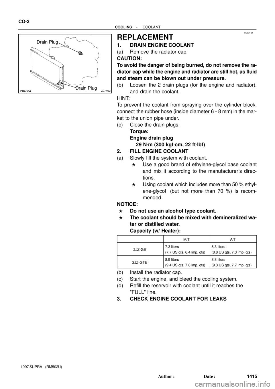
Z07402
Drain Plug
Drain Plug CO-2
- COOLINGCOOLANT
1415 Author�: Date�:
1997 SUPRA (RM502U)
REPLACEMENT
1. DRAIN ENGINE COOLANT
(a) Remove the radiator cap.
CAUTION:
To avoid the danger of being burned, do not remove the ra-
diator cap while the engine and radiator are still hot, as fluid
and steam can be blown out under pressure.
(b) Loosen the 2 drain plugs (for the engine and radiator),
and drain the coolant.
HINT:
To prevent the coolant from spraying over the cylinder block,
connect the rubber hose (inside diameter 6 - 8 mm) in the mar-
ket to the union pipe under.
(c) Close the drain plugs.
Torque:
Engine drain plug
29 N´m (300 kgf´cm, 22 ft´lbf)
2. FILL ENGINE COOLANT
(a) Slowly fill the system with coolant.
�Use a good brand of ethylene-glycol base coolant
and mix it according to the manufacturer's direc-
tions.
�Using coolant which includes more than 50 % ethyl-
ene-glycol (but not more than 70 %) is recom-
mended.
NOTICE:
�Do not use an alcohol type coolant.
�The coolant should be mixed with demineralized wa-
ter or distilled water.
Capacity (w/ Heater):
M/TA/T
2JZ-GE7.3 liters
(7.7 US qts, 6.4 lmp. qts)8.3 liters
(8.8 US qts, 7.3 lmp. qts)
2JZ-GTE8.9 liters
(9.4 US qts, 7.8 lmp. qts)8.8 liters
(9.3 US qts, 7.7 lmp. qts)
(b) Install the radiator cap.
(c) Start the engine, and bleed the cooling system.
(d) Refill the reservoir with coolant until it reaches the
ºFULLº line.
3. CHECK ENGINE COOLANT FOR LEAKS