Page 330 of 1807
BR0GE-02
W02667
Brake Booster
� Gasket
Level Warning Switch Connector Master Cylinder
2JZ-GTE Engine :
Vacuum Hose
Clamp
� Non-reusable part BR-10
- BRAKEBRAKE MASTER CYLINDER
1810 Author�: Date�:
1997 SUPRA (RM502U)
BRAKE MASTER CYLINDER
COMPONENTS
Page 332 of 1807
BR0GF-01
W02790
SST
W02791
BR-12
- BRAKEBRAKE MASTER CYLINDER
1812 Author�: Date�:
1997 SUPRA (RM502U)
REMOVAL
1. DISCONNECT LEVEL WARNING SWITCH
CONNECTOR
2. DRAW OUT FLUID WITH SYRINGE
NOTICE:
Do not let brake fluid remain on a painted surface. Wash it
off immediately.
3. DISCONNECT BRAKE LINES
Using SST, disconnect the brake lines from the master cylinder.
SST 09023-00100
Torque: 15 N´m (155 kgf´cm, 11 ft´lbf)
4. REMOVE MASTER CYLINDER
(a) Remove the 2 nuts.
Torque: 13 N´m (130 kgf´cm, 9 ft´lbf)
(b) 2JZ-GE Engine:
Remove the master cylinder and gasket from the brake
booster.
(c) 2JZ-GTE Engine:
Remove the vacuum hose clamp, master cylinder and
gasket from the brake booster.
Page 336 of 1807
BR0GL-03
W02993
Pedal Bracket Stay
Return Spring
Clevis Pin ClevisClip � Gasket Brake Booster
� Gasket Master Cylinder
Level Warning Switch Connector
2JZ-GTE Engine:
Vacuum Hose Clamp
� Non-reusable part
- BRAKEBRAKE BOOSTER ASSEMBLY
BR-19
1819 Author�: Date�:
1997 SUPRA (RM502U)
COMPONENTS
Page 358 of 1807

BR0HO-02
R07206
SST
SST
- BRAKEPROPORTIONING AND BY-PASS VALVE (P & B
VALVE)BR-65
1865 Author�: Date�:
1997 SUPRA (RM502U)
PROPORTIONING AND BY-PASS VALVE (P & B VALVE)
ON-VEHICLE INSPECTION
1. INSTALL LSPV GAUGE (SST) AND BLEED AIR
SST 09709-29017
2. RAISE MASTER CYLINDER PRESSURE AND CHECK REAR BRAKE CALIPER PRESSURE
3. INSTALL LSPV GAUGE (SST) AND BLEED AIR
SST 09709-29017
4. RAISE MASTER CYLINDER PRESSURE AND CHECK REAR BRAKE CALIPER PRESSURE
2JZ-GE Engine:
Master cylinder pressureRear brake caliper pressure
2,942 kPa (30 kgf/cm2, 427 psi)2,942 kPa (30 kgf/cm2, 427 psi)
7,845 kPa (80 kgf/cm2, 1,138 psi)4,756 kPa (48.5 kgf/cm2, 690 psi)
2JZ-GTE Engine:
Master cylinder pressureRear brake caliper pressure
2,452 kPa (25 kgf/cm2, 356 psi)2,452 kPa (25 kgf/cm2, 356 psi)
7,845 kPa (80 kgf/cm2, 1,138 psi)4,452 kPa (45.4 kgf/cm2, 646 psi)
If the rear brake caliper pressure is incorrect, replace the master cylinder.
5. BLEED BRAKE SYSTEM (See page BR-5)
6. CHECK FOR FLUID LEAKAGE
Page 360 of 1807

W03289
W03290
W03291
W03292
- BRAKEABS ACTUATOR (2JZ-GTE)
BR-73
1873 Author�: Date�:
1997 SUPRA (RM502U)
(c) Place the ºSHEET Nº (SST) on the actuator checker.
SST 09990-00410
4. INSPECT BRAKE ACTUATOR OPERATION OF
FRONT LH WHEEL
(a) Start the engine, and run it at idle.
(b) Turn the selector switch of the actuator checker to
ºFRONT RHº position.
(c) Push and hold in the MOTOR switch for a few seconds.
Make sure that you can hear the motor running.
(d) Depress the brake pedal and hold it for about 15 seconds,
and check that the pedal does not go down.
(e) With your foot still applying onto the brake pedal, push
MOTOR switch and check that the brake pedal does not
pulsate.
(f) Depress the brake pedal and hold it. As you hold the ped-
al down, push and hold in the MAIN push switch for a few
seconds. Check that the pedal does not go down.
NOTICE:
Do not keep pushing the MAIN push switch more than 10
seconds.
(g) With your foot still applying onto the brake pedal, release
the MAIN push switch and check that the pedal goes
down.
(h) With your foot still applying onto the brake pedal, push the
MOTOR switch and check that the brake pedal returns.
(i) Release the brake pedal.
5. INSPECT FOR OTHER WHEEL
(a) Turn the selector switch to the ºREAR LHº position, and
inspect the ºREAR LHº wheel.
(b) Repeating (c) to (i) in the step 4, check the actuator opera-
tion similarly.
Page 361 of 1807
BR-74
- BRAKEABS ACTUATOR (2JZ-GTE)
1874 Author�: Date�:
1997 SUPRA (RM502U)
(c) Similarly, inspect the ºREAR RHº and ºFRONT RHº wheel.
HINT:
When inspecting the ºFRONT RHº wheel, push the FRONT LH
switch instead of the MAIN push switch. This makes it possible
to inspect wherever the selector switch position indicates.
6. PUSH MOTOR SWITCH
(a) Push and hold in the MOTOR switch for a few seconds.
(b) Stop the engine.
7. DISCONNECT ACTUATOR CHECKER (SST) FROM
ACTUATOR
(a) Disconnect the actuator checker (SST) and sub-wire har-
nesses (SST) from the actuator.
SST 09990-00150, 09990-00250, 09990-00300,
09990-00360, 09990-00410
(b) Connect the 2 actuator connectors.
(c) Clear the DTC (See page DI-442).
Page 376 of 1807

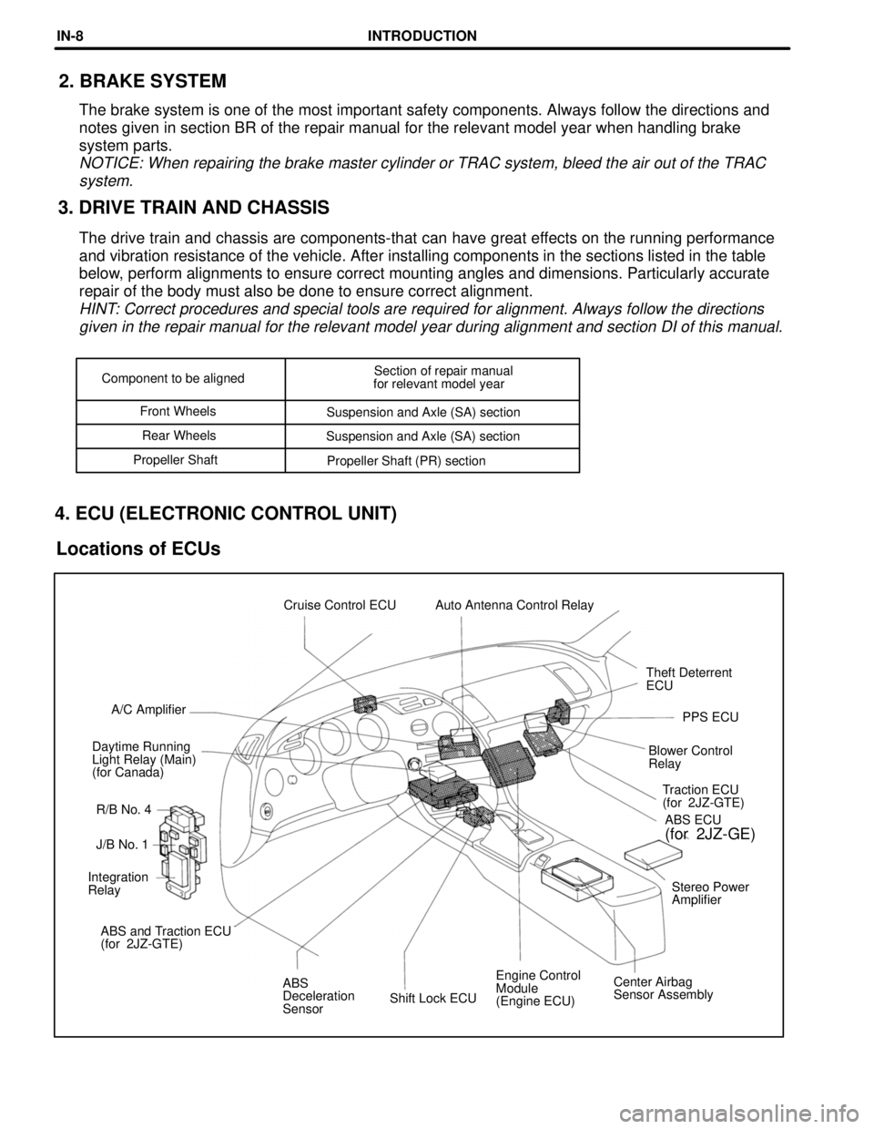
Shift Lock ECUEngine Control
Module
(Engine ECU)Center Airbag
Sensor Assembly ABS
Deceleration
Sensor ABS and Traction ECU
(for 2JZ-GTE)Stereo Power
Amplifier Integration
RelayJ/B No. 1Traction ECU
(for 2JZ-GTE)
R/B No. 4 Daytime Running
Light Relay (Main)
(for Canada)Blower Control
RelayPPS ECU A/C AmplifierTheft Deterrent
ECU Cruise Control ECU Auto Antenna Control Relay
ABS ECU
(for 2JZ-GE)
Component to be alignedSection of repair manual
for relevant model year
Front Wheels
Suspension and Axle (SA) section
Rear Wheels
Suspension and Axle (SA) section
Propeller Shaft
Propeller Shaft (PR) section
3. DRIVE TRAIN AND CHASSIS2. BRAKE SYSTEM
The brake system is one of the most important safety components. Always follow the directions and
notes given in section BR of the repair manual for the relevant model year when handling brake
system parts.
NOTICE: When repairing the brake master cylinder or TRAC system, bleed the air out of the TRAC
system.
The drive train and chassis are components-that can have great effects on the running performance
and vibration resistance of the vehicle. After installing components in the sections listed in the table
below, perform alignments to ensure correct mounting angles and dimensions. Particularly accurate
repair of the body must also be done to ensure correct alignment.
HINT: Correct procedures and special tools are required for alignment. Always follow the directions
given in the repair manual for the relevant model year during alignment and section DI of this manual.
4. ECU (ELECTRONIC CONTROL UNIT)
Locations of ECUs
INTRODUCTIONIN-8
Page 381 of 1807

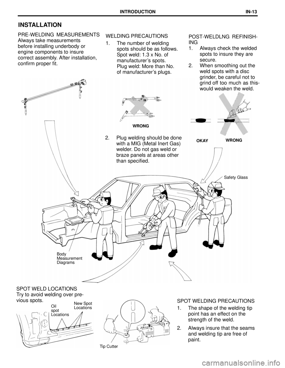
SPOT WELD LOCATIONS
Try to avoid welding over pre-
vious spots.
New Spot
Locations
WELDING PRECAUTIONS
1. The number of welding
spots should be as follows.
Spot weld: 1.3 x No. of
manufacturer's spots.
Plug weld: More than No.
of manufacturer's plugs.
INSTALLATION
POST-WELDLNG REFINISH-
ING
1. Always check the welded
spots to insure they are
secure.
2. When smoothing out the
weld spots with a disc
grinder, be careful not to
grind off too much as this-
would weaken the weld. PRE-WELDING MEASUREMENTS
Always take measurements
before installing underbody or
engine components to insure
correct assembly. After installation,
confirm proper fit.
WRONG
WRONG
OKAY
2. Plug welding should be done
with a MIG (Metal Inert Gas)
welder. Do not gas weld or
braze panels at areas other
than specified.
Safety Glass
Body
Measurement
Diagrams
SPOT WELDING PRECAUTIONS
1. The shape of the welding tip
point has an effect on the
strength of the weld.
2. Always insure that the seams
and welding tip are free of
paint.
Oil
spot
Locations
Tip Cutter
INTRODUCTIONIN-13