Page 138 of 1807
N16962
N08733
- AIR CONDITIONINGCONDENSER
AC-45
2193 Author�: Date�:
1997 SUPRA (RM502U)
(d) Push the condenser toward radiator and remove the liq-
uid tube piping clamp.
Torque: 4.1 N´m (42 kgf´cm, 36 in.´lbf)
(e) Push the condenser toward engine and pull it upward.
HINT:
At the time of installation, please refer to the following item.
If condenser is replaced, add compressor oil to the condenser.
Add 40 cc (1.4 fl.oz.)
Compressor oil: ND-OIL 8 or equivalent
Page 142 of 1807
AC0QY-01
AC-54
- AIR CONDITIONINGEXPANSION VALVE
2202 Author�: Date�:
1997 SUPRA (RM502U)
EXPANSION VALVE
ON-VEHICLE INSPECTION
1. CHECK QUANTITY OF GAS DURING REFRIGERATION CYCLE
2. SET ON MANIFOLD GAUGE SET
(See page AC-18)
3. RUN ENGINE
(a) Run the engine at 1,500 rpm for at least 5 minutes.
(b) Then check that the high pressure reading is 1.37 - 1.57 MPa (14 - 16 kgf/cm
2, 199 - 228 psi).
4. CHECK EXPANSION VALVE
If the expansion valve is faulty, the low pressure reading will drop to 0 kPa (0 kgf/cm
2, 0 psi).
HINT:
When the low pressure drops to 0 kPa (0 kgf/cm
2, 0 psi), check the receiver's IN and OUT sides for no tem-
perature difference.
Page 144 of 1807
AC0R1-01
N19660
- AIR CONDITIONINGWATER VALVE
AC-57
2205 Author�: Date�:
1997 SUPRA (RM502U)
WATER VALVE
REMOVAL
1. DRAIN ENGINE COOLANT FROM RADIATOR
HINT:
It is not to drain out all coolant.
2. REMOVE INSTRUMENT PANEL
(See page BO-54)
3. REMOVE AIR MIX SERVOMOTOR
(See page AC-65)
4. REMOVE WATER VALVE
Remove the 5 screws and water valve.
Page 150 of 1807
N08382
N08399
AC-70
- AIR CONDITIONINGSENSOR
2218 Author�: Date�:
1997 SUPRA (RM502U)
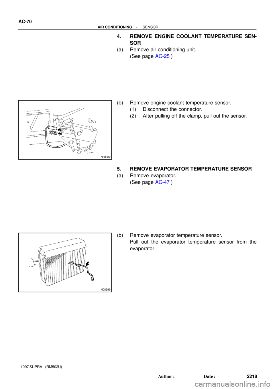
4. REMOVE ENGINE COOLANT TEMPERATURE SEN-
SOR
(a) Remove air conditioning unit.
(See page AC-25)
(b) Remove engine coolant temperature sensor.
(1) Disconnect the connector.
(2) After pulling off the clamp, pull out the sensor.
5. REMOVE EVAPORATOR TEMPERATURE SENSOR
(a) Remove evaporator.
(See page AC-47)
(b) Remove evaporator temperature sensor.
Pull out the evaporator temperature sensor from the
evaporator.
Page 151 of 1807

196 kPa
(2.0 kgf´cm
2, 28 psi)
OFF (No Continuity)3, 140 kPa
(32.0 kgf´cm2, 455 psi)
OFF (No Conti")
N08405
AC0RF-02
Z13470
Magnetic Clutch Control
Low Pressure Side High Pressure Side
ON (Continuity)
196 kPa
(2.0 kgf´cm
2, 28 psi)
OFF (No Continuity)3, 140 kPa
(32.0 kgf´cm2, 455 psi)
OFF (No Continuity)
Z13471
Cooling Fan Control
1, 520 kPa
(15.5 kgf´cm2, 220psi)
ON
(Continuity)
OFF
(No Continity)
1, 226 kPa
(12.5 kgf´cm
2, 178psi)
- AIR CONDITIONINGPRESSURE SWITCH
AC-73
2221 Author�: Date�:
1997 SUPRA (RM502U)
PRESSURE SWITCH
ON-VEHICLE INSPECTION
1. SET ON MANIFOLD GAUGE SET
(See page AC-18)
2. DISCONNECT CONNECTOR FROM PRESSURE
SWITCH
3. RUN ENGINE AT APPROX. 2,000 RPM
4. Magnetic Clutch Control:
INSPECT PRESSURE SWITCH OPERATION
( ): 2JZ-GTE
(a) Connect the positive (+) lead from the ohmmeter to termi-
nal 4 (1) and the negative (-) lead to terminal 1 (2).
(b) Check continuity between terminals when refrigerant
pressure is changed, as shown in the illustration.
If operation is not as specified, replace the pressure switch.
5. 2JZ-GTE Engine Models:
Condenser Fan Control:
INSPECT PRESSURE SWITCN OPERATION
(a) Connect the positive (+) lead from the ohmmeter to termi-
nal 2 and the negative (-) lead to terminal 3.
(b) Check continuity between terminals when refrigerant
pressure is changed, as shwn in the illustration.
If operation is not as specified, replace the pressure switch.
6. STOP ENGINE AND SET OFF MANIFOLD GAUGE SET
7. CONNECT CONNECTOR TO PRESSURE SWITCH
Page 155 of 1807
I03527
AC0RQ-01
- AIR CONDITIONINGENGINE COOLANT TEMPERATURE (ECT) SWITCH
AC-85
2233 Author�: Date�:
1997 SUPRA (RM502U)
ENGINE COOLANT
TEMPERATURE (ECT) SWITCH
REMOVAL
1. REMOVE ENGINE UNDER COVER
2. DRAIN ENGINE COOLANT
HINT:
It is not necessary to drain out all coolant.
3. REMOVE SWITCH
(a) Disconnect the connector.
(b) Remove the switch.
Torque: 7.4 N´m (75 kgf´cm, 65 in.´lbf)
HINT:
At the time of installation, please refer to the following item.
Lubricate a new O-ring with soapy water and install the switch.
Page 156 of 1807
P01924
AC0RR-01
AC-86
- AIR CONDITIONINGENGINE COOLANT TEMPERATURE (ECT) SWITCH
2234 Author�: Date�:
1997 SUPRA (RM502U)
INSPECTION
INSPECT ECT SWITCH CONTINUITY
(a) Using an ohmmeter, check the no continuity exists be-
tween the terminals when the coolant temperature is a
above 100°C (212°F).
If there is continuity, replace the switch.
(b) Using an ohmmeter, check the continuity existsbetween
the terminals when the coolant temperature is below
91°C (196°F).
If there is no continuity, replace the switch.
Page 160 of 1807
 Taillight does not light with light control SW in TAIL.
1. Taillight Relay (J/B No.1)
2. Integration Relay
3. Li")
BE-4
- BODY ELECTRICALBODY ELECTRICAL SYSTEM
1982 Author�: Date�:
1997 SUPRA (RM502U) Taillight does not light with light control SW in TAIL.
1. Taillight Relay (J/B No.1)
2. Integration Relay
3. Light Control Switch
4. Wire HarnessBE-17
BE-13
BE-17
Taillight does not go out with light control SW in OFF.
1. Taillight Relay (J/B No.1)
2. Integration Relay
3. Light Control switch
4. Wire HarnessBE-17
BE-13
BE-17
Headlight and Taillight do not light with engine running and light
control SW in OFF.
1. GAUGE Fuse (J/B No.1)
2. Generator L Terminal
3. D.R.L. Relay
4. D.R.L. No.2 Relay (R/B No.2)
5. D.R.L. No.3 Relay
6. Parking Brake Switch
7. Wire Harness
BE-17
BE-17
BE-17
BE-43
FOG LIGHT SYSTEM
SymptomSuspect AreaSee page
Fog light does not light with light control SW HEAD.
(Headlight is normal.)
1. FOG Fuse (R/B No.2)
2. HEAD Fuse (R/B No.2)
3. Fog Light Relay (R/B No.2)
4. Fog Light Switch
5. Wire Harness
BE-23
BE-23
Fog light does not light with light control SW HEAD.
(Headlight does not light)1. Headlight and Taillight system
2. Wire HarnessBE-15
Only one light does not light.1. Bulb
2. Wire Harness
TURN SIGNAL HAZARD WARNING SYSTEM
SymptomSuspect AreaSee page
ºHazardº and ºTurnº do not light up.
1. Hazard Warning Switch
2. Turn Signal Flasher
3. Wire HarnessBE-26
BE-26
The flashing frequency is abnormal.
1. Bulb
2. Turn Signal Flasher
3. Wire Harness
BE-26
Hazard warning light does not light up.
(Turn is normal.)1. HAZ-HORN Fuse (R/B No.2)
2. Wire Harness
Hazard warning light does not light up in one direction.1. Hazard Warning Switch
2. Wire HarnessBE-26
Turn signal does not light up.
(Combination meter, wiper and washer do not operate.)
1. TURN Fuse (J/B No.1)
2. Ignition Switch
3. Turn Signal Switch
4. Wire Harness
BE-13
BE-26
Turn signal does not light up.
1. TURN Fuse (J/B No.1)
2. Turn Signal Switch
3. Wire Harness
BE-26
Turn signal does not light up in one direction.1. Turn Signal Switch
2. Wire HarnessBE-26
Only one bulb does not light up.1. Bulb
2. Wire Harness