Page 532 of 1807
B01771
Air Cleaner and MAF Meter Assembly
No.1 Air Hose
Air Cleaner Duct
Upper Radiator Support
Radiator Assembly
Radiator Reservoir Hose
Electric Cooling
Fan Connector
ECT Switch
Connector
No.2 Fan Shroud
No.2 Air Tube Lower
Radiator
Support
Hose Clamp
Oil Cooler Tube
Engine Under Cover Drive Belt
A/T
x 16Battery
Insulator
Water Pump Pulley
Fan and Fluid Coupling Assembly
PS Pump Pulley
Battery Tray
Battery
MAF Meter Connector
Hold-Down
Clamp
2JZ-GTE
- COOLINGWATER PUMP
CO-5
1418 Author�: Date�:
1997 SUPRA (RM502U)
Page 538 of 1807

INSTALLATION
1. INSTALL WATER PUMP
(a) Install a new O-ring to t")
CO08O-01
P03945
New
O-Ring
P02574
New Gasket
S00913
A
B A
B
AB
BB
- COOLINGWATER PUMP
CO-1 1
1424 Author�: Date�:
1997 SUPRA (RM502U)
INSTALLATION
1. INSTALL WATER PUMP
(a) Install a new O-ring to the cylinder block.
(b) Install the drain hose.
(c) Install a new gasket to the water pump.
(d) Connect the water pump to the water bypass pipe. Do not
install the nut yet.
(e) Install the water pump with the 2 bolts (A) and 4 bolts (B).
Torque: 21 N´m (210 kgf´cm, 15 ft´lbf)
HINT:
Hand tighten the (A) bolts first.
(f) Install the 2 nuts holding the No.2 water bypass pipe to
the water pump.
Torque: 21 N´m (210 kgf´cm, 15 ft´lbf)
(g) 2JZ-GTE:
Connect the No.3 turbo water hose to the water pump.
(h) 2JZ-GE:
Install the connector bracket (for crankshaft position sen-
sor connector) with the bolt.
(i) 2JZ-GE:
Install the engine clamp bracket with the bolt.
(j) Install the generator with the bolt and nut.
Torque: 40 N´m (400 kgf´cm, 30 ft´lbf)
2. 2JZ-GE:
INSTALL NO.1 WATER BYPASS PIPE AND
WATER BYPASS OUTLET
(a) Install 2 new O-rings to the No.1 water bypass pipe.
(b) Install a new O-ring and the water bypass outlet with the
2 bolts.
Torque: 9.0 N´m (90 kgf´cm, 80 in.´lbf)
3. 2JZ-GTE:
INSTALL NO.1 WATER BYPASS PIPE AND
WATER OUTLET
(a) Install 2 new O-rings to the No.1 water bypass pipe.
(b) Apply soapy water to the O-rings.
(c) Install the No.1 water bypass pipe to the water pump.
Page 540 of 1807
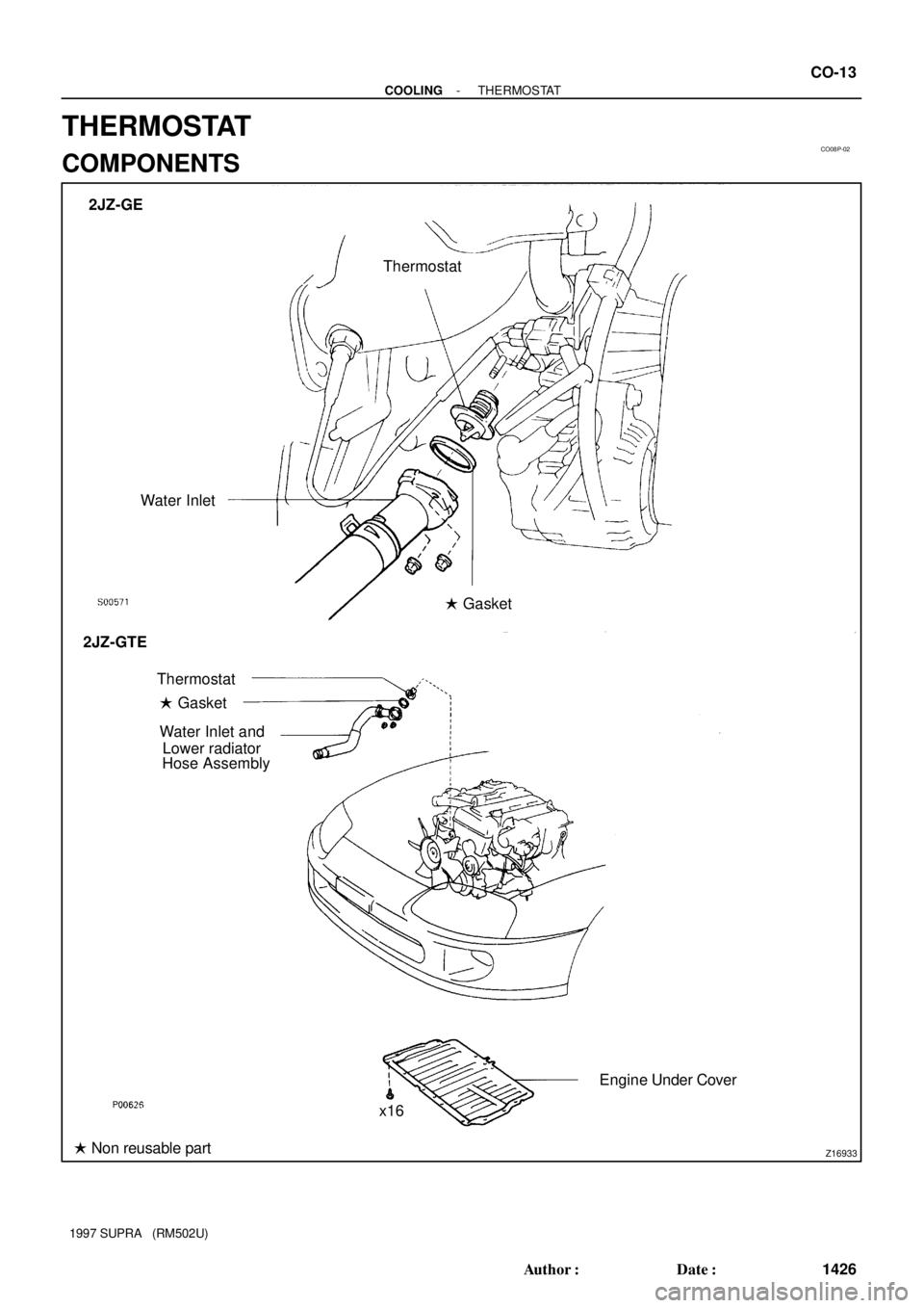
CO08P-02
Z16933
2JZ-GE
Thermostat
Water Inlet
� Gasket
Hose AssemblyLower radiator Water Inlet and
Engine Under Cover � Gasket
� Non reusable partThermostat 2JZ-GTE
x16
- COOLINGTHERMOSTAT
CO-13
1426 Author�: Date�:
1997 SUPRA (RM502U)
THERMOSTAT
COMPONENTS
Page 541 of 1807
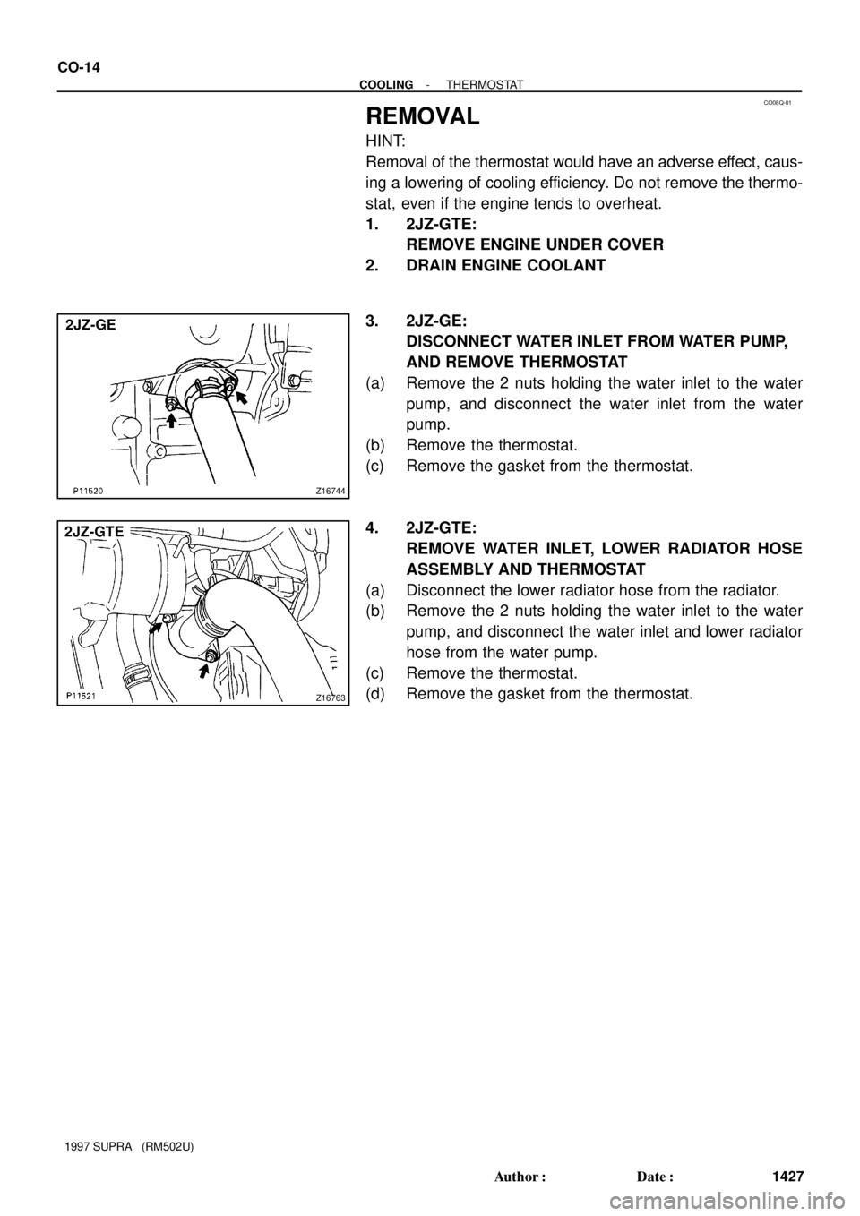
CO08Q-01
Z16744
2JZ-GE
Z16763
2JZ-GTE CO-14
- COOLINGTHERMOSTAT
1427 Author�: Date�:
1997 SUPRA (RM502U)
REMOVAL
HINT:
Removal of the thermostat would have an adverse effect, caus-
ing a lowering of cooling efficiency. Do not remove the thermo-
stat, even if the engine tends to overheat.
1. 2JZ-GTE:
REMOVE ENGINE UNDER COVER
2. DRAIN ENGINE COOLANT
3. 2JZ-GE:
DISCONNECT WATER INLET FROM WATER PUMP,
AND REMOVE THERMOSTAT
(a) Remove the 2 nuts holding the water inlet to the water
pump, and disconnect the water inlet from the water
pump.
(b) Remove the thermostat.
(c) Remove the gasket from the thermostat.
4. 2JZ-GTE:
REMOVE WATER INLET, LOWER RADIATOR HOSE
ASSEMBLY AND THERMOSTAT
(a) Disconnect the lower radiator hose from the radiator.
(b) Remove the 2 nuts holding the water inlet to the water
pump, and disconnect the water inlet and lower radiator
hose from the water pump.
(c) Remove the thermostat.
(d) Remove the gasket from the thermostat.
Page 543 of 1807
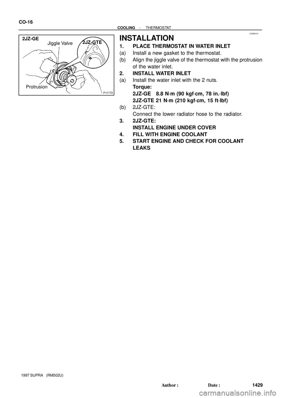
CO08S-01
P11770
Jiggle Valve
Protrusion 2JZ-GE
2JZ-GTE CO-16
- COOLINGTHERMOSTAT
1429 Author�: Date�:
1997 SUPRA (RM502U)
INSTALLATION
1. PLACE THERMOSTAT IN WATER INLET
(a) Install a new gasket to the thermostat.
(b) Align the jiggle valve of the thermostat with the protrusion
of the water inlet.
2. INSTALL WATER INLET
(a) Install the water inlet with the 2 nuts.
Torque:
2JZ-GE 8.8 N´m (90 kgf´cm, 78 in.´lbf)
2JZ-GTE 21 N´m (210 kgf´cm, 15 ft´lbf)
(b) 2JZ-GTE:
Connect the lower radiator hose to the radiator.
3. 2JZ-GTE:
INSTALL ENGINE UNDER COVER
4. FILL WITH ENGINE COOLANT
5. START ENGINE AND CHECK FOR COOLANT
LEAKS
Page 545 of 1807

ON-VEHICLE INSPECTION
1. REMOVE RADIATOR CAP
CAUTION:
To avoid")
Z00570
Radiator Cap Tester
30° or More
Radiator Cap
P11504
CO08U-01
CO-18
- COOLINGRADIATOR
1431 Author�: Date�:
1997 SUPRA (RM502U)
ON-VEHICLE INSPECTION
1. REMOVE RADIATOR CAP
CAUTION:
To avoid the danger of being burned, do not remove the ra-
diator cap while the engine and radiator are still hot, as fluid
and steam can be blown out under pressure.
2. INSPECT RADIATOR CAP
NOTICE:
�If the radiator cap has contaminations, always rinse
it with water.
�When performing steps (a) and (b) below, keep the ra-
diator pump tester at an angle of over 30° above the
horizontal.
(a) Before using a radiator cap tester, wet the relief valve and
pressure valve with engine coolant or water.
(b) Using a radiator cap tester, slowly pump the tester and
check that air is coming from the vacuum valve.
Pump speed: 1 push/ (3 seconds or more)
NOTICE:
Push the pump at a constant speed.
If air is not coming from the vacuum valve, replace the radiator
cap.
(c) Pump the tester and measure the relief valve opening
pressure.
Pump speed: 1 push within 1 second
NOTICE:
This pump speed is for the first pump only (in order to close
the vacuum valve). After this, the pump speed can be re-
duced.
Standard opening pressure:
93 - 123 kPa (0.95 - 1.25 kgf/cm
2, 13.5 - 17.8 psi)
Minimum opening pressure:
78 kPa (0.8 kgf/cm
2, 11.4 psi)
HINT:
Use the tester's maximum reading as the opening pressure.
If the opening pressure is less than minimum, replace the radia-
tor cap.
3. INSPECT COOLING SYSTEM FOR LEAKS
(a) Fill the radiator with coolant, and attach a radiator cap tes-
ter.
(b) Warm up the engine.
(c) Pump it to 147 kPa (1.5 kgf/cm
2, 21.3 psi), and check that
the pressure does not drop.
If the pressure drops, check the hoses, radiator or water pump
for leaks.
If no external leaks are found, check the heater core, cylinder
block and cylinder head.
4. REINSTALL RADIATOR CAP
Page 547 of 1807
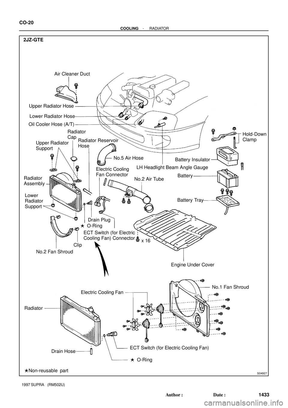
S04927
Air Cleaner Duct
Upper Radiator Hose
Hold-Down
Clamp Radiator
Cap
Battery Insulator
Battery Lower Radiator Hose
Oil Cooler Hose (A/T)
Upper Radiator
Support
Radiator
Assembly
� O-Ring
No.2 Fan ShroudBattery Tray
Engine Under Cover x 16 Electric Cooling
Fan Connector
Drain Plug Radiator Reservoir
Hose
No.5 Air Hose
No.2 Air Tube
ECT Switch (for Electric
Cooling Fan) Connector
Radiator
�Non-reusable partNo.1 Fan Shroud Clip Lower
Radiator
Support 2JZ-GTE
Drain HoseECT Switch (for Electric Cooling Fan)
� O-Ring Electric Cooling FanLH Headlight Beam Angle Gauge CO-20
- COOLINGRADIATOR
1433 Author�: Date�:
1997 SUPRA (RM502U)
Page 549 of 1807
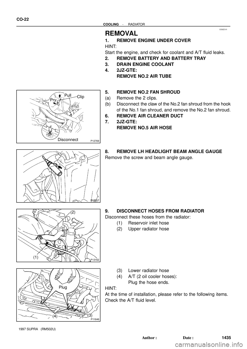
CO0ZZ-01
P12769
PryClip Pull
Disconnect
P12217
P13162
(2)
(1)
P11646
Plug
(4)(3) CO-22
- COOLINGRADIATOR
1435 Author�: Date�:
1997 SUPRA (RM502U)
REMOVAL
1. REMOVE ENGINE UNDER COVER
HINT:
Start the engine, and check for coolant and A/T fluid leaks.
2. REMOVE BATTERY AND BATTERY TRAY
3. DRAIN ENGINE COOLANT
4. 2JZ-GTE:
REMOVE NO.2 AIR TUBE
5. REMOVE NO.2 FAN SHROUD
(a) Remove the 2 clips.
(b) Disconnect the claw of the No.2 fan shroud from the hook
of the No.1 fan shroud, and remove the No.2 fan shroud.
6. REMOVE AIR CLEANER DUCT
7. 2JZ-GTE:
REMOVE NO.5 AIR HOSE
8. REMOVE LH HEADLIGHT BEAM ANGLE GAUGE
Remove the screw and beam angle gauge.
9. DISCONNECT HOSES FROM RADIATOR
Disconnect these hoses from the radiator:
(1) Reservoir inlet hose
(2) Upper radiator hose
(3) Lower radiator hose
(4) A/T (2 oil cooler hoses):
Plug the hose ends.
HINT:
At the time of installation, please refer to the following items.
Check the A/T fluid level.