Page 2639 of 3342
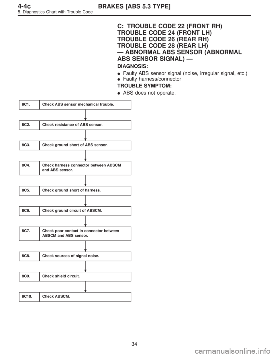
C: TROUBLE CODE 22 (FRONT RH)
TROUBLE CODE 24 (FRONT LH)
TROUBLE CODE 26 (REAR RH)
TROUBLE CODE 28 (REAR LH)
—ABNORMAL ABS SENSOR (ABNORMAL
ABS SENSOR SIGNAL)—
DIAGNOSIS:
�Faulty ABS sensor signal (noise, irregular signal, etc.)
�Faulty harness/connector
TROUBLE SYMPTOM:
�ABS does not operate.
8C1.Check ABS sensor mechanical trouble.
8C2.Check resistance of ABS sensor.
8C3.Check ground short of ABS sensor.
8C4.Check harness connector between ABSCM
and ABS sensor.
8C5.Check ground short of harness.
8C6.Check ground circuit of ABSCM.
8C7.Check poor contact in connector between
ABSCM and ABS sensor.
8C8.Check sources of signal noise.
8C9.Check shield circuit.
8C10.Check ABSCM.
�
�
�
�
�
�
�
�
�
34
4-4cBRAKES [ABS 5.3 TYPE]
8. Diagnostics Chart with Trouble Code
Page 2640 of 3342
WIRING DIAGRAM:
B4M1035
8C1CHECK ABS SENSOR MECHANICAL
TROUBLE.
: Tightening torque:
32±10 N⋅m (3.3±1.0 kg-m, 24±7 ft-lb)
Are the ABS sensor installation bolts tight-
ened securely?
: Go to next.
: Tighten ABS sensor installation bolts securely.
: Tightening torque:
13±3 N⋅m (1.3±0.3 kg-m, 9±2.2 ft-lb)
Are the tone wheel installation bolts tight-
ened securely?
: Go to next step.
: Tighten tone wheel installation bolts securely.
35
4-4cBRAKES [ABS 5.3 TYPE]
8. Diagnostics Chart with Trouble Code
Page 2641 of 3342
 Measure tone wheel to pole piece gap over entire
perimeter of the wheel.
: Is the gap within the specifications shown
in the following table?
SpecificationsFront wheel Rear wheel
0.9—1.4")
G4M0700
1) Measure tone wheel to pole piece gap over entire
perimeter of the wheel.
: Is the gap within the specifications shown
in the following table?
SpecificationsFront wheel Rear wheel
0.9—1.4 mm
(0.035—0.055 in)0.7—1.2 mm
(0.028—0.047 in)
G4M0701
: Go to next.
: Adjust the gap.
NOTE:
Adjust the gap using spacer (Part No. 26755AA000). If
spacers cannot correct the gap, replace worn sensor or
worn tone wheel.
: Is an oscilloscope available?
: Go to next step.
: Go to step 13).
B4M0815A
2) Raise all four wheels of ground.
3) Turn ignition switch OFF.
4) Disconnect connector from ABS control module.
5) Remove band.
6) Remove cable clamp cover.
7) Remove screws securing connector cover.
CAUTION:
Do not allow harness to catch on adjacent parts dur-
ing installation.
B4M1026
8) Remove connector cover.
B4M1027A
NOTE:
�To install, reverse above removal procedures.
�Align connector cover rib with connector hole before
installation.
36
4-4cBRAKES [ABS 5.3 TYPE]
8. Diagnostics Chart with Trouble Code
Page 2642 of 3342
 Connect connector to ABS control module.
10) Connect the oscilloscope to the ABS control module
connector in accordance with trouble code.
11) Turn ignition switch ON.
B4M0816A
12) Rotate wheels an")
9) Connect connector to ABS control module.
10) Connect the oscilloscope to the ABS control module
connector in accordance with trouble code.
11) Turn ignition switch ON.
B4M0816A
12) Rotate wheels and measure voltage at specified fre-
quency.
NOTE:
When this inspection is completed, the ABS control mod-
ule sometimes stores the trouble code 29.
TROUBLE CODE / Connector & terminal:
22 / (F49) No. 14 (+)—No. 15 (�)
24 / (F49) No. 49 (+)—No. 19 (�)
26 / (F49) No. 18 (+)—No. 46 (�)
28 / (F49) No. 16 (+)—No. 17 (�)
Specified voltage: 0.12—1 V (When it is 20 Hz.)
: Is oscilloscope pattern smooth, as shown in
figure?
: Go to step8C2.
: Go to next step.
13) Remove disc rotor from hub in accordance with trouble
code.
: Is the ABS sensor pole piece or the tone
wheel contaminated by dirt or other foreign
matter?
: Thoroughly remove dirt or other foreign matter.
: Go to next.
: Are there broken or damaged teeth in the
ABS sensor pole piece or the tone wheel?
: Replace ABS sensor or tone wheel.
: Go to next step.
14) Measure hub runout.
: Is the runout less than 0.05 mm (0.0020 in)?
: Go to step8C2.
: Repair hub.
37
4-4cBRAKES [ABS 5.3 TYPE]
8. Diagnostics Chart with Trouble Code
Page 2643 of 3342
B4M0806B
B4M1036A
8C2
CHECK RESISTANCE OF ABS SENSOR.
1) Turn ignition switch OFF.
2) Disconnect connector from ABS sensor.
3) Measure resistance between ABS sensor connector ter-
minals.
: Trouble code/Connector & terminal
22/to (B6) No. 1—No. 2
24/to (B15) No. 1—No. 2
26/to (P8) No. 1—No. 2
28/to (P9) No. 1—No. 2
Is resistance 0.8—1.2 kΩ?
: Go to step8C3.
: Replace ABS sensor.
B4M0818B
B4M1042A
8C3CHECK GROUND SHORT OF ABS SEN-
SOR.
Measure resistance between ABS sensor and chassis
ground.
: Trouble code/Connector & terminal
22/to (B6) No. 1—Chassis ground
24/to (B15) No. 1—Chassis ground
26/to (P8) No. 1—Chassis ground
28/to (P9) No. 1—Chassis ground
Is resistance more than 1 MΩ?
: Go to step8C4.
: Replace ABS sensor.
38
4-4cBRAKES [ABS 5.3 TYPE]
8. Diagnostics Chart with Trouble Code
Page 2644 of 3342
 Connect connector to ABS sensor.
2) Disconnect connector from ABS control module.
3) Measure resistance at ABSCM connector terminal")
B4M0809A
8C4CHECK HARNESS CONNECTOR
BETWEEN ABSCM AND ABS SENSOR.
1) Connect connector to ABS sensor.
2) Disconnect connector from ABS control module.
3) Measure resistance at ABSCM connector terminals.
: Trouble code/Connector & terminal
22/(F49) No. 14—No. 15
24/(F49) No. 49—No. 19
26/(F49) No. 18—No. 46
28/(F49) No. 16—No. 17
Is resistance 0.8—1.2 kΩ?
: Go to step8C5.
: Repair harness connector between ABSCM and
ABS sensor.
B4M0820A
8C5
CHECK GROUND SHORT OF HARNESS.
Measure resistance between ABSCM connector and chas-
sis ground.
: Trouble code/Connector & terminal
22/(F49) No. 14—Chassis ground
24/(F49) No. 49—Chassis ground
26/(F49) No. 18—Chassis ground
28/(F49) No. 16—Chassis ground
Is resistance more than 1 MΩ?
: Go to step8C6.
: Repair harness connector between ABSCM and
ABS sensor.
B4M0814A
8C6
CHECK GROUND CIRCUIT OF ABSCM.
Measure resistance between ABSCM and chassis ground.
: Connector & terminal
(F49) No. 1—GND
(F49) No. 55—GND
Is resistance less than 0.5Ω?
: Go to step8C7.
: Repair ABSCM ground harness.
39
4-4cBRAKES [ABS 5.3 TYPE]
8. Diagnostics Chart with Trouble Code
Page 2645 of 3342
8C7CHECK POOR CONTACT IN CONNEC-
TOR BETWEEN ABSCM AND ABS SEN-
SOR.
: Is there poor contact in connectors between
ABSCM and ABS sensor?
: Repair connector.
: Go to step8C8.
8C8
CHECK SOURCES OF SIGNAL NOISE.
: Is the car telephone or the wireless trans-
mitter properly installed?
: Go to next.
: Properly install the car telephone or the wireless
transmitter.
: Are noise sources (such as an antenna)
installed near the sensor harness?
: Install the noise sources apart from the sensor
harness.
: Go to step8C9.
B4M1038A
8C9
CHECK SHIELD CIRCUIT.
1) Connect all connectors.
2) Measure resistance between shield connector and
chassis ground.
: Trouble code/Connector & terminal
22/(B100) No. 11—Chassis ground
24/(B100) No. 2—Chassis ground
26/(P1) No. 8—Chassis ground
28/(P1) No. 3—Chassis ground
Is resistance less than 0.5Ω?
: Go to step8C10.
: Repair shield harness.
40
4-4cBRAKES [ABS 5.3 TYPE]
8. Diagnostics Chart with Trouble Code
Page 2647 of 3342
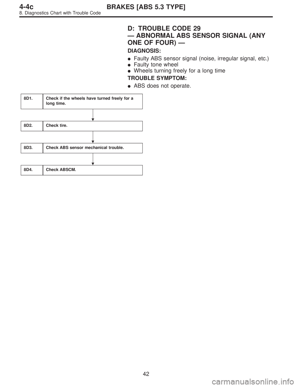
D: TROUBLE CODE 29
—ABNORMAL ABS SENSOR SIGNAL (ANY
ONE OF FOUR)—
DIAGNOSIS:
�Faulty ABS sensor signal (noise, irregular signal, etc.)
�Faulty tone wheel
�Wheels turning freely for a long time
TROUBLE SYMPTOM:
�ABS does not operate.
8D1.Check if the wheels have turned freely for a
long time.
8D2.Check tire.
8D3.Check ABS sensor mechanical trouble.
8D4.Check ABSCM.
�
�
�
42
4-4cBRAKES [ABS 5.3 TYPE]
8. Diagnostics Chart with Trouble Code

Are the ABS sensor installation bolts tight-
ened securely?
: Go to next.")
 Turn ignition switch OFF.
2) Disconnect connector from ABS sensor.
3) Measure resistance between ABS sensor connector ter-
minals.
: Trouble co")