Page 2611 of 3342
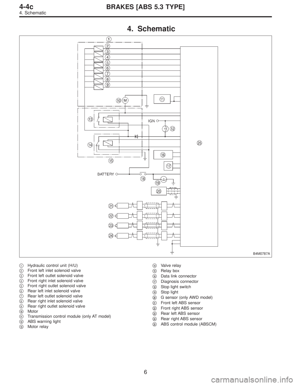
4. Schematic
B4M0787A
�1Hydraulic control unit (H/U)
�
2Front left inlet solenoid valve
�
3Front left outlet solenoid valve
�
4Front right inlet solenoid valve
�
5Front right outlet solenoid valve
�
6Rear left inlet solenoid valve
�
7Rear left outlet solenoid valve
�
8Rear right inlet solenoid valve
�
9Rear right outlet solenoid valve
�
10Motor
�
11Transmission control module (only AT model)
�
12ABS warning light
�
13Motor relay�
14Valve relay
�
15Relay box
�
16Data link connector
�
17Diagnosis connector
�
18Stop light switch
�
19Stop light
�
20G sensor (only AWD model)
�
21Front left ABS sensor
�
22Front right ABS sensor
�
23Rear left ABS sensor
�
24Rear right ABS sensor
�
25ABS control module (ABSCM)
6
4-4cBRAKES [ABS 5.3 TYPE]
4. Schematic
Page 2613 of 3342
Front left wheel 49—19
0.12—1V
(When it is 20 Hz.) Front right wheel 14—15
Rear le")
Contents Terminal No.Input/Output signal
Measured value and measuring conditions
ABS sensor
(Wheel
speed
sensor)Front left wheel 49—19
0.12—1V
(When it is 20 Hz.) Front right wheel 14—15
Rear left wheel 16—17
Rear right wheel 18—46
Hydraulic
control unitSolenoid
valveFront left outlet 51—1
10—13 V when the valve is OFF and
less than 1.5 V when the valve is ON. Front right outlet 3—1
Rear left outlet 4—1
Rear right outlet 50—1
Front left inlet 24—1
Front right inlet 30—1
Rear left inlet 31—1
Rear right inlet 23—1
Relay boxValve relay power supply 27—110—13 V when ignition switch is ON.
Valve relay coil 47—1 Less than 1.5 V when ignition switch is ON.
Motor relay coil 22—1More than 10 V when the ABS control does not operate still
and less than 1.5 V when ABS operates.
Motor monitoring 10—1Less than 1.5 V when the ABS control does not operate still
and more than 10 V when ABS operates.
G sensor
(AWD
model only)power supply 8—45 4.75—5.25 V
ground 45—
output 7—45 2.3±0.2 V when vehicle is in horizontal position.
Stop light switch 36—1Less than 1.5 V when the stop light is OFF and more than
4.5 V when the stop light is ON.
ABS warning light 54—1Less than 1.5 V during 1.5 seconds when ignition switch is
ON, and 10—14 V after 1.5 seconds.
AT ABS signal
(AT model only)12—1Less than 1.5 V when the ABS control does not operate still
and more than 5.5 V when ABS operates.
ABS operation signal monitor 39—1Less than 1.5 V when the ABS control does not operate still
and more than 5.5 V when ABS operates.
Select
monitorData is received. 11—1 Less than 1.5 V when no data is received.
Data is sent. 38—1 4.75—5.25 V when no data is sent.
Diagnosis
connectorTerminal No. 3 5—110—14 V when ignition switch is ON.
Terminal No. 6 13—110—14 V when ignition switch is ON.
Power supply 28—110—14 V when ignition switch is ON.
Grounding line 1—
Grounding line 55—
8
4-4cBRAKES [ABS 5.3 TYPE]
5. Control Module I/O Signal
Page 2632 of 3342

8. Diagnostics Chart with Trouble Code
A: LIST OF TROUBLE CODE
Trouble code Contents of diagnosis Ref. to
11Start code
�Trouble code is shown after start code.
�Only start code is shown in normal condition.—
21
Abnormal ABS sensor
(Open circuit or input voltage too high)Front right ABS sensor
4-4c [T8B0] 23 Front left ABS sensor
25 Rear right ABS sensor
27 Rear left ABS sensor
22
Abnormal ABS sensor
(Abnormal ABS sensor signal)Front right ABS sensor
4-4c [T8C0] 24 Front left ABS sensor
26 Rear right ABS sensor
28 Rear left ABS sensor
29 Any one of four 4-4c [T8D0]
31
Abnormal solenoid valve circuit(s) in
hydraulic unitFront right inlet valve 4-4c [T8E0]
32 Front right outlet valve 4-4c [T8F0]
33 Front left inlet valve 4-4c [T8E0]
34 Front left outlet valve 4-4c [T8F0]
35 Rear right inlet valve 4-4c [T8E0]
36 Rear right outlet valve 4-4c [T8F0]
37 Rear left inlet valve 4-4c [T8E0]
38 Rear left outlet valve 4-4c [T8F0]
41 Abnormal ABS control module 4-4c [T8G0]
42 Source voltage is low. 4-4c [T8H0]
44 A combination of AT control abnormals 4-4c [T8I0]
46 Abnormal G sensor power supply voltage 4-4c [T8J0]
51 Abnormal valve relay4-4c [T8K0]
52 Abnormal motor and/or motor relay 4-4c [T8L0]
54 Abnormal stop light switch 4-4c [T8M0]
56 Abnormal G sensor output voltage 4-4c [T8N0]
27
4-4cBRAKES [ABS 5.3 TYPE]
8. Diagnostics Chart with Trouble Code
Page 2633 of 3342
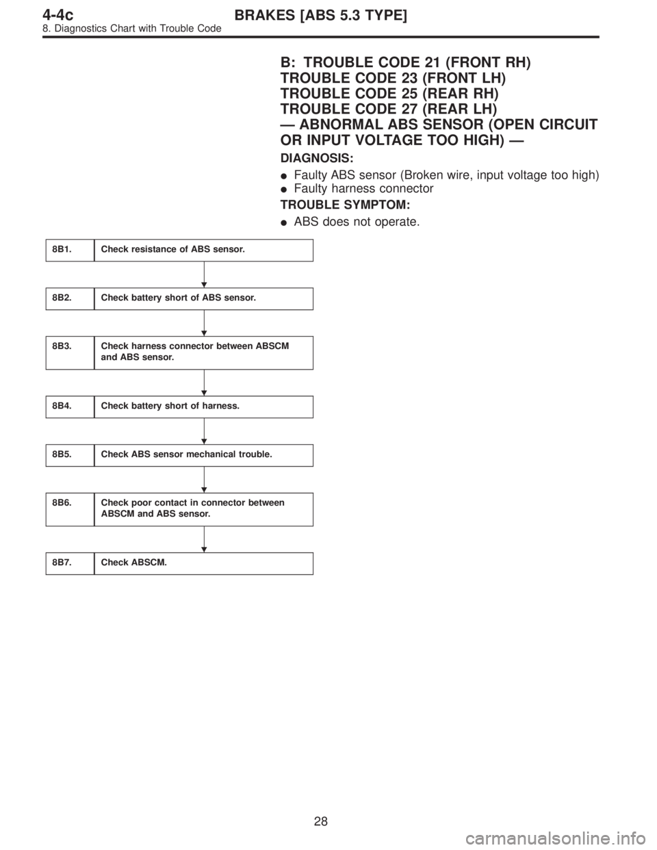
B: TROUBLE CODE 21 (FRONT RH)
TROUBLE CODE 23 (FRONT LH)
TROUBLE CODE 25 (REAR RH)
TROUBLE CODE 27 (REAR LH)
—ABNORMAL ABS SENSOR (OPEN CIRCUIT
OR INPUT VOLTAGE TOO HIGH)—
DIAGNOSIS:
�Faulty ABS sensor (Broken wire, input voltage too high)
�Faulty harness connector
TROUBLE SYMPTOM:
�ABS does not operate.
8B1.Check resistance of ABS sensor.
8B2.Check battery short of ABS sensor.
8B3.Check harness connector between ABSCM
and ABS sensor.
8B4.Check battery short of harness.
8B5.Check ABS sensor mechanical trouble.
8B6.Check poor contact in connector between
ABSCM and ABS sensor.
8B7.Check ABSCM.
�
�
�
�
�
�
28
4-4cBRAKES [ABS 5.3 TYPE]
8. Diagnostics Chart with Trouble Code
Page 2635 of 3342
 Turn ignition switch to OFF.
2) Disconnect connector from ABS sensor.
3) Measure resistance of ABS sensor connector terminals.
: Trouble code/C")
B4M0806B
B4M1036A
8B1
CHECK RESISTANCE OF ABS SENSOR.
1) Turn ignition switch to OFF.
2) Disconnect connector from ABS sensor.
3) Measure resistance of ABS sensor connector terminals.
: Trouble code/Connector & terminal
21/to (B6) No. 1—No. 2
23/to (B15) No. 1—No. 2
25/to (P8) No. 1—No. 2
27/to (P9) No. 1—No. 2
Is resistance 0.8—1.2 kΩ?
: Go to step8B2.
: Replace ABS sensor.
B4M0807B
B4M1037A
8B2CHECK BATTERY SHORT OF ABS SEN-
SOR.
1) Disconnect connector from ABSCM.
2) Turn ignition switch to ON.
3) Measure voltage between ABS sensor and chassis
ground.
: Trouble code/Connector & terminal
21/to (B6) No. 1 (+)—Chassis ground (�)
23/to (B15) No. 1 (+)—Chassis ground (�)
25/to (P8) No. 1 (+)—Chassis ground (�)
27/to (P9) No. 1 (+)—Chassis ground (�)
Is voltage 0 V?
: Go to next step.
: Replace ABS sensor.
4) Turn ignition switch to OFF.
5) Measure voltage between ABS sensor and chassis
ground.
: Trouble code/Connector & terminal
21/to (B6) No. 1 (+)—Chassis ground (�)
23/to (B15) No. 1 (+)—Chassis ground (�)
25/to (P8) No. 1 (+)—Chassis ground (�)
27/to (P9) No. 1 (+)—Chassis ground (�)
Is voltage 0 V?
: Go to step8B3.
: Replace ABS sensor.
30
4-4cBRAKES [ABS 5.3 TYPE]
8. Diagnostics Chart with Trouble Code
Page 2636 of 3342
 Connect connector to ABS sensor.
2) Measure resistance between ABSCM connector termi-
nals.
: Trouble code/Connector & terminal
21/")
B4M0809A
8B3CHECK HARNESS CONNECTOR
BETWEEN ABSCM AND ABS SENSOR.
1) Connect connector to ABS sensor.
2) Measure resistance between ABSCM connector termi-
nals.
: Trouble code/Connector & terminal
21/(F49) No. 14—No. 15
23/(F49) No. 49—No. 19
25/(F49) No. 18—No. 46
27/(F49) No. 16—No. 17
Is resistance 0.8—1.2 kΩ?
: Go to step8B4.
: Repair harness connector between ABSCM and
ABS sensor.
B4M0810A
8B4
CHECK BATTERY SHORT OF HARNESS.
1) Turn ignition switch to ON.
2) Measure voltage between ABSCM connector and chas-
sis ground.
: Trouble code/Connector & terminal
21/(F49) No. 14 (+)—Chassis ground (�)
23/(F49) No. 49 (+)—Chassis ground (�)
25/(F49) No. 18 (+)—Chassis ground (�)
27/(F49) No. 16 (+)—Chassis ground (�)
Is voltage 0 V?
: Go to next step.
: Repair harness between ABSCM and ABS sen-
sor.
3) Turn ignition switch to OFF.
4) Measure voltage between ABSCM connector and chas-
sis ground.
: Trouble code/Connector & terminal
21/(F49) No. 14 (+)—Chassis ground (�)
23/(F49) No. 49 (+)—Chassis ground (�)
25/(F49) No. 18 (+)—Chassis ground (�)
27/(F49) No. 16 (+)—Chassis ground (�)
Is voltage 0 V?
: Go to step8B5.
: Repair harness between ABSCM and ABS sen-
sor.
31
4-4cBRAKES [ABS 5.3 TYPE]
8. Diagnostics Chart with Trouble Code
Page 2637 of 3342

Are the ABS sensor installation bolts tight-
ened securely?
: Go to next.
: Tighten ABS sensor in")
8B5CHECK ABS SENSOR MECHANICAL
TROUBLE.
: Tightening torque:
32±10 N⋅m (3.3±1.0 kg-m, 24±7 ft-lb)
Are the ABS sensor installation bolts tight-
ened securely?
: Go to next.
: Tighten ABS sensor installation bolts securely.
: Tightening torque:
13±3 N⋅m (1.3±0.3 kg-m, 9±2.2 ft-lb)
Are the tone wheel installation bolts tight-
ened securely?
: Go to next step.
: Tighten tone wheel installation bolts securely.
G4M0700
1) Measure tone wheel-to-pole piece gap over entire
perimeter of the wheel.
: Is the gap within the specifications shown
in the following table?
SpecificationsFront wheel Rear wheel
0.9—1.4 mm
(0.035—0.055 in)0.7—1.2 mm
(0.028—0.047 in)
G4M0701
: Go to next step.
: Adjust the gap.
NOTE:
Adjust the gap using spacers (Part No. 26755AA000). If
spacers cannot correct the gap, replace worn sensor or
worn tone wheel.
2) Measure hub runout.
: Is the runout less than 0.05 mm (0.0020 in)?
: Go to step8B6.
: Repair hub.
32
4-4cBRAKES [ABS 5.3 TYPE]
8. Diagnostics Chart with Trouble Code
Page 2638 of 3342
8B6CHECK POOR CONTACT IN CONNEC-
TOR BETWEEN ABSCM AND ABS SEN-
SOR.
: Is there poor contact in connectors between
ABSCM and ABS sensor?
: Repair connector.
: Go to step8B7.
8B7
CHECK ABSCM.
1) Connect all connectors.
2) Erase the memory.
3) Perform inspection mode.
4) Read out the trouble code.
: Is the same trouble code as in the current
diagnosis still being output?
: Replace ABSCM.
: Go to next.
: Are other trouble codes being output?
: Proceed with the diagnosis corresponding to the
trouble code.
: A temporary poor contact.
NOTE:
Check harness and connectors between ABSCM and ABS
sensor.
33
4-4cBRAKES [ABS 5.3 TYPE]
8. Diagnostics Chart with Trouble Code
 Connec")