Page 2728 of 3342
![SUBARU LEGACY 1997 Service Repair Manual B: LIST OF TROUBLE CODE
Code Display screen (FB1) Contents of diagnosis Ref. to
—ERROR 3 (1) Select monitor communication failure 4-4c [T10C0]
11 NO TROUBLEAlthough no trouble appears on the select](/manual-img/17/57434/w960_57434-2727.png "SUBARU LEGACY 1997 Service Repair Manual B: LIST OF TROUBLE CODE
Code Display screen (FB1) Contents of diagnosis Ref. to
—ERROR 3 (1) Select monitor communication failure 4-4c [T10C0]
11 NO TROUBLEAlthough no trouble appears on the select")
B: LIST OF TROUBLE CODE
Code Display screen (FB1) Contents of diagnosis Ref. to
—ERROR 3 (1) Select monitor communication failure 4-4c [T10C0]
11 NO TROUBLEAlthough no trouble appears on the select monitor display, the ABS
warning light remains on.4-4c [T10D0]
21 FR. SS HARD Open circuit or input voltage too high of FR sensor 4-4c [T10E0]
22 FR. SS SOFT Abnormal ABS sensor signal of FR sensor 4-4c [T10I0]
23 FL. SS HARD Open circuit or input voltage too high of FL sensor 4-4c [T10F0]
24 FL. SS SOFT Abnormal ABS sensor signal of FL sensor 4-4c [T10J0]
25 RR. SS HARD Open circuit or input voltage too high of RR sensor 4-4c [T10G0]
26 RR. SS SOFT Abnormal ABS sensor signal of RR sensor 4-4c [T10K0]
27 RL. SS HARD Open circuit or input voltage too high of RL sensor 4-4c [T10H0]
28 RL. SS SOFT Abnormal ABS sensor signal of RL sensor 4-4c [T10L0]
29 EITHER. SS SOFT Abnormal ABS sensor signal (any one of four) 4-4c [T10M0]
31 FR. EV VALVE Abnormal FR inlet valve 4-4c [T10N0]
32 FR. AV VALVE Abnormal FR outlet valve 4-4c [T10R0]
33 FL. EV VALVE Abnormal FL inlet valve 4-4c [T10O0]
34 FL. AV VALVE Abnormal FL outlet valve 4-4c [T10S0]
35 RR. EV VALVE Abnormal RR inlet valve 4-4c [T10P0]
36 RR. AV VALVE Abnormal RR outlet valve 4-4c [T10T0]
37 RL. EV VALVE Abnormal RL inlet valve 4-4c [T10Q0]
38 RL. AV VALVE Abnormal RL outlet valve 4-4c [T10U0]
41 ECU Abnormal ABSCM 4-4c [T10V0]
42 LOW VOLTAGE Source voltage is low. 4-4c [T10W0]
44CCM LINE A combination of AT control abnormals (ABS not in control) 4-4c [T10X0]
CCM OPEN A combination of AT control abnormals (ABS in control) 4-4c [T10Y0]
46GS POWER OVER G sensor line voltage too high 4-4c [T10Z0]
GS POWER LOW G sensor line voltage too low 4-4c [T10AA0]
51V. RELAY Abnormal valve relay 4-4c [T10AB0]
V. RELAY ON Valve relay ON failure 4-4c [T10AC0]
52M. RELAY OPEN Open circuit of motor relay 4-4c [T10AD0]
M. RELAY ON Motor relay ON failure 4-4c [T10AE0]
MOTOR Abnormal motor 4-4c [T10AF0]
54 BLS Abnormal stop light switch 4-4c [T10AG0]
56G SENSOR LINE Open or short circuit of G sensor 4-4c [T10AH0]
G SENSOR +B Battery short of G sensor 4-4c [T10AI0]
G SENSOR Hµ Abnormal G sensor high µ output 4-4c [T10AJ0]
G SENSOR STICK G sensor output is stuck. 4-4c [T10AK0]
NOTE:
High µ means high friction coefficient against road sur-
face.
123
4-4cBRAKES [ABS 5.3 TYPE]
10. Diagnostics Chart with Select Monitor
Page 2737 of 3342
B4M0945
E: 21 FR. SS HARD
—ABNORMAL FRONT RH ABS SENSOR
(OPEN CIRCUIT OR INPUT VOLTAGE TOO
HIGH)—
B4M0946
F: 23 FL. SS HARD
—ABNORMAL FRONT LH ABS SENSOR
(OPEN CIRCUIT OR INPUT VOLTAGE TOO
HIGH)—
B4M0947
G: 25 RR. SS HARD
—ABNORMAL REAR RH ABS SENSOR
(OPEN CIRCUIT OR INPUT VOLTAGE TOO
HIGH)—
B4M0948
H: 27 RL. SS HARD
—ABNORMAL REAR LH ABS SENSOR
(OPEN CIRCUIT OR INPUT VOLTAGE TOO
HIGH)—
132
4-4cBRAKES [ABS 5.3 TYPE]
10. Diagnostics Chart with Select Monitor
Page 2738 of 3342
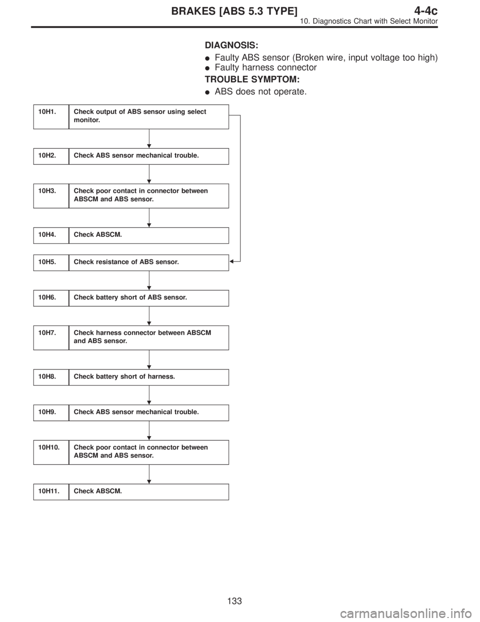
DIAGNOSIS:
�Faulty ABS sensor (Broken wire, input voltage too high)
�Faulty harness connector
TROUBLE SYMPTOM:
�ABS does not operate.
10H1.Check output of ABS sensor using select
monitor.
�
10H2.Check ABS sensor mechanical trouble.
10H3.Check poor contact in connector between
ABSCM and ABS sensor.
10H4.Check ABSCM.
10H5.Check resistance of ABS sensor.
10H6.Check battery short of ABS sensor.
10H7.Check harness connector between ABSCM
and ABS sensor.
10H8.Check battery short of harness.
10H9.Check ABS sensor mechanical trouble.
10H10.Check poor contact in connector between
ABSCM and ABS sensor.
10H11.Check ABSCM.
�
�
�
�
�
�
�
�
�
133
4-4cBRAKES [ABS 5.3 TYPE]
10. Diagnostics Chart with Select Monitor
Page 2740 of 3342

B4M0922
10H1CHECK OUTPUT OF ABS SENSOR
USING SELECT MONITOR.
Read the ABS sensor output corresponding to the faulty
system in the select monitor function mode.
NOTE:
The select monitor display shows that the front right wheel
is rotating at 30 km/h.
: Does the speed indicated on the display
change in response to the speedometer
reading during acceleration/deceleration
when the steering wheel is in the straight-
ahead position?
: Go to step10H2.
: Go to step10H5.
10H2CHECK ABS SENSOR MECHANICAL
TROUBLE.
: Tightening torque:
32±10 N⋅m (3.3±1.0 kg-m, 24±7 ft-lb)
Are the ABS sensor installation bolts tight-
ened securely?
: Go to next.
: Tighten ABS sensor installation bolts securely.
: Tightening torque:
13±3 N⋅m (1.3±0.3 kg-m, 9±2.2 ft-lb)
Are the tone wheel installation bolts tight-
ened securely?
: Go to next step.
: Tighten tone wheel installation bolts securely.
G4M0700
1) Measure tone wheel-to-pole piece gap over entire
perimeter of the wheel.
: Is the gap within the specifications shown
in the following table?
SpecificationsFront wheel Rear wheel
0.9—1.4 mm
(0.035—0.055 in)0.7—1.2 mm
(0.028—0.047 in)
135
4-4cBRAKES [ABS 5.3 TYPE]
10. Diagnostics Chart with Select Monitor
Page 2741 of 3342
G4M0701
: Go to next step.
: Adjust the gap.
NOTE:
Adjust the gap using spacers (Part No. 26755AA000). If
spacers cannot correct the gap, replace worn sensor or
worn tone wheel.
2) Measure hub runout.
: Is the runout less than 0.05 mm (0.0020 in)?
: Go to step10H3.
: Repair hub.
10H3CHECK POOR CONTACT IN CONNEC-
TOR BETWEEN ABSCM AND ABS SEN-
SOR.
: Is there poor contact in connectors between
ABSCM and ABS sensor?
: Repair connector.
: Go to step10H4.
10H4
CHECK ABSCM.
1) Connect all connectors.
2) Erase the memory.
3) Perform inspection mode.
4) Read out the trouble code.
: Is the same trouble code as in the current
diagnosis still being output?
: Replace ABSCM.
: Go to next.
: Are other trouble codes being output?
: Proceed with the diagnosis corresponding to the
trouble code.
: A temporary poor contact.
NOTE:
Check harness and connectors between ABSCM and ABS
sensor.
136
4-4cBRAKES [ABS 5.3 TYPE]
10. Diagnostics Chart with Select Monitor
Page 2742 of 3342
 Turn ignition switch to OFF.
2) Disconnect connector from ABS sensor.
3) Measure resistance of ABS sensor connector terminals.
: Trouble code/")
B4M0806B
B4M1036A
10H5
CHECK RESISTANCE OF ABS SENSOR.
1) Turn ignition switch to OFF.
2) Disconnect connector from ABS sensor.
3) Measure resistance of ABS sensor connector terminals.
: Trouble code/Connector & terminal
21/to (B6) No. 1—No. 2
23/to (B15) No. 1—No. 2
25/to (P8) No. 1—No. 2
27/to (P9) No. 1—No. 2
Is resistance 0.8—1.2 kΩ?
: Go to step10H6.
: Replace ABS sensor.
B4M0807B
B4M1037A
10H6CHECK BATTERY SHORT OF ABS SEN-
SOR.
1) Disconnect connector from ABSCM.
2) Turn ignition switch to ON.
3) Measure voltage between ABS sensor and chassis
ground.
: Trouble code/Connector & terminal
21/to (B6) No. 1 (+)—Chassis ground (�)
23/to (B15) No. 1 (+)—Chassis ground (�)
25/to (P8) No. 1 (+)—Chassis ground (�)
27/to (P9) No. 1 (+)—Chassis ground (�)
Is voltage 0 V?
: Go to next step.
: Replace ABS sensor.
4) Turn ignition switch to OFF.
5) Measure voltage between ABS sensor and chassis
ground.
: Trouble code/Connector & terminal
21/to (B6) No. 1 (+)—Chassis ground (�)
23/to (B15) No. 1 (+)—Chassis ground (�)
25/to (P8) No. 1 (+)—Chassis ground (�)
27/to (P9) No. 1 (+)—Chassis ground (�)
Is voltage 0 V?
: Go to step10H7.
: Replace ABS sensor.
137
4-4cBRAKES [ABS 5.3 TYPE]
10. Diagnostics Chart with Select Monitor
Page 2743 of 3342
 Connect connector to ABS sensor.
2) Measure resistance between ABSCM connector termi-
nals.
: Trouble code/Connector & terminal
21")
B4M0809A
10H7CHECK HARNESS CONNECTOR
BETWEEN ABSCM AND ABS SENSOR.
1) Connect connector to ABS sensor.
2) Measure resistance between ABSCM connector termi-
nals.
: Trouble code/Connector & terminal
21/(F49) No. 14—No. 15
23/(F49) No. 49—No. 19
25/(F49) No. 18—No. 46
27/(F49) No. 16—No. 17
Is resistance 0.8—1.2 kΩ?
: Go to step10H8.
: Repair harness connector between ABSCM and
ABS sensor.
B4M0810A
10H8
CHECK BATTERY SHORT OF HARNESS.
1) Turn ignition switch to ON.
2) Measure voltage between ABSCM connector and chas-
sis ground.
: Trouble code/Connector & terminal
21/(F49) No. 14—Chassis ground
23/(F49) No. 49—Chassis ground
25/(F49) No. 18—Chassis ground
27/(F49) No. 16—Chassis ground
Is voltage 0 V?
: Go to next step.
: Repair harness between ABSCM and ABS sen-
sor.
3) Turn ignition switch to OFF.
4) Measure voltage between ABSCM connector and chas-
sis ground.
: Trouble code/Connector & terminal
21/(F49) No. 14—Chassis ground
23/(F49) No. 49—Chassis ground
25/(F49) No. 18—Chassis ground
27/(F49) No. 16—Chassis ground
Is voltage 0 V?
: Go to step10H9.
: Repair harness between ABSCM and ABS sen-
sor.
138
4-4cBRAKES [ABS 5.3 TYPE]
10. Diagnostics Chart with Select Monitor
Page 2744 of 3342

Are the ABS sensor installation bolts tight-
ened securely?
: Go to next.
: Tighten ABS sensor i")
10H9CHECK ABS SENSOR MECHANICAL
TROUBLE.
: Tightening torque:
32±10 N⋅m (3.3±1.0 kg-m, 24±7 ft-lb)
Are the ABS sensor installation bolts tight-
ened securely?
: Go to next.
: Tighten ABS sensor installation bolts securely.
: Tightening torque:
13±3 N⋅m (1.3±0.3 kg-m, 9±2.2 ft-lb)
Are the tone wheel installation bolts tight-
ened securely?
: Go to next step.
: Tighten tone wheel installation bolts securely.
G4M0700
1) Measure tone wheel-to-pole piece gap over entire
perimeter of the wheel.
: Is the gap within the specifications shown
in the following table?
SpecificationsFront wheel Rear wheel
0.9—1.4 mm
(0.035—0.055 in)0.7—1.2 mm
(0.028—0.047 in)
G4M0701
: Go to next step.
: Adjust the gap.
NOTE:
Adjust the gap using spacers (Part No. 26755AA000). If
spacers cannot correct the gap, replace worn sensor or
worn tone wheel.
2) Measure hub runout.
: Is the runout less than 0.05 mm (0.0020 in)?
: Go to step10H10.
: Repair hub.
139
4-4cBRAKES [ABS 5.3 TYPE]
10. Diagnostics Chart with Select Monitor
—
B4M0946
F: 23 FL. SS HARD
—ABNORMAL FRONT LH ABS SENSOR
(OPEN CIRCUIT OR INPUT VOLTAGE TOO
HIGH)")
. If
spacers cannot correct the gap, replace worn sensor or
worn tone wheel.
2) Measure hub runout.")