Page 2755 of 3342
10L13
CHECK SOURCES OF SIGNAL NOISE.
: Is the car telephone or the wireless trans-
mitter properly installed?
: Go to next.
: Properly install the car telephone or the wireless
transmitter.
: Are noise sources (such as an antenna)
installed near the sensor harness?
: Install the noise sources apart from the sensor
harness.
: Go to step10L14.
B4M1038A
10L14
CHECK SHIELD CIRCUIT.
1) Connect all connectors.
2) Measure resistance between shield connector and
chassis ground.
: Trouble code/Connector & terminal
22/(B100) No. 11—Chassis ground
24/(B100) No. 2—Chassis ground
26/(P1) No. 8—Chassis ground
28/(P1) No. 3—Chassis ground
Is resistance less than 0.5Ω?
: Go to step10L15.
: Repair shield harness.
150
4-4cBRAKES [ABS 5.3 TYPE]
10. Diagnostics Chart with Select Monitor
Page 2757 of 3342
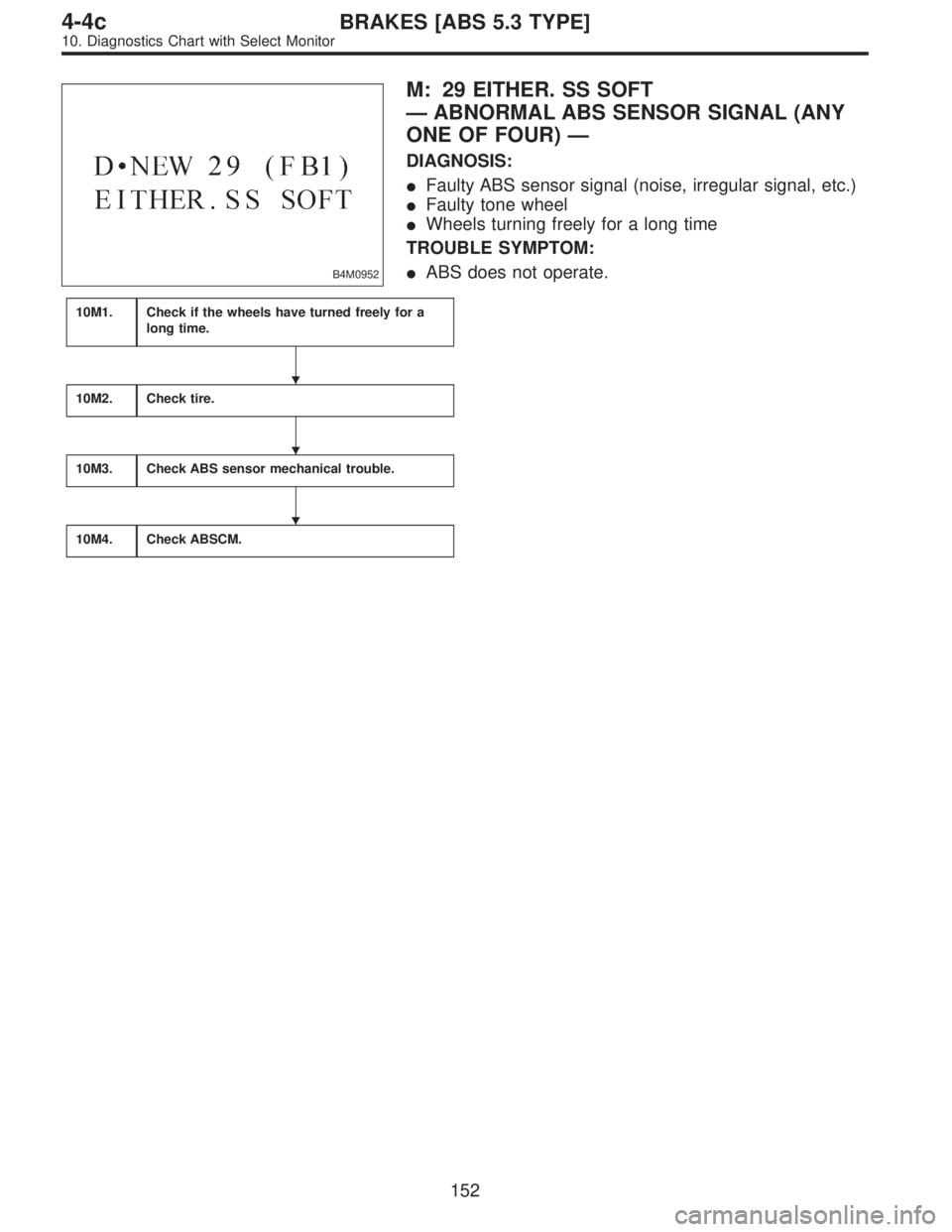
B4M0952
M: 29 EITHER. SS SOFT
—ABNORMAL ABS SENSOR SIGNAL (ANY
ONE OF FOUR)—
DIAGNOSIS:
�Faulty ABS sensor signal (noise, irregular signal, etc.)
�Faulty tone wheel
�Wheels turning freely for a long time
TROUBLE SYMPTOM:
�ABS does not operate.
10M1.Check if the wheels have turned freely for a
long time.
10M2.Check tire.
10M3.Check ABS sensor mechanical trouble.
10M4.Check ABSCM.
�
�
�
152
4-4cBRAKES [ABS 5.3 TYPE]
10. Diagnostics Chart with Select Monitor
Page 2759 of 3342
10M2
CHECK TIRE.
: Are the tire specifications correct?
: Go to next.
: Replace tire.
: Is the tire worn excessively?
: Replace tire.
: Go to next.
: Is the tire pressure correct?
: Go to step10M3.
: Adjust tire pressure.
10M3CHECK ABS SENSOR MECHANICAL
TROUBLE.
: Tightening torque:
32±10 N⋅m (3.3±1.0 kg-m, 24±7 ft-lb)
Are the ABS sensor installation bolts tight-
ened securely?
: Go to next.
: Tighten ABS sensor installation bolts securely.
: Tightening torque:
13±3 N⋅m (1.3±0.3 kg-m, 9±2.2 ft-lb)
Are the ABS sensor installation bolts tight-
ened securely?
: Go to next step.
: Tighten ABS sensor installation bolts securely.
G4M0700
1) Measure tone wheel to pole piece gap over entire
perimeter of the wheel.
: Is the gap within the specifications shown
in the following table?
SpecificationsFront wheel Rear wheel
0.9—1.4 mm
(0.035—0.055 in)0.7—1.2 mm
(0.028—0.047 in)
154
4-4cBRAKES [ABS 5.3 TYPE]
10. Diagnostics Chart with Select Monitor
Page 2760 of 3342
. If
spacers cannot correct the gap, replace worn sensor or
worn tone wheel.
: Is an oscilloscope availab")
G4M0701
: Go to next.
: Adjust the gap.
NOTE:
Adjust the gap using spacer (Part No. 26755AA000). If
spacers cannot correct the gap, replace worn sensor or
worn tone wheel.
: Is an oscilloscope available?
: Go to next step.
: Go to step 10).
2) Raise all four wheels of ground.
3) Turn ignition switch OFF.
4) Disconnect connector from ABS control module.
5) Disconnect connector cover from connector.
6) Connect connector to ABS control module.
7) Connect the oscilloscope to the ABS control module
connector.
8) Turn ignition switch ON.
B4M0816A
9) Rotate wheels and measure voltage at specified fre-
quency.
NOTE:
When this inspection is completed, the ABS control mod-
ule sometimes stores the trouble code 29.
TROUBLE CODE / Connector & terminal:
(F49) No. 14 (+)—No. 15 (�) (Front RH)
(F49) No. 49 (+)—No. 19 (�) (Front LH)
(F49) No. 18 (+)—No. 46 (�) (Rear RH)
(F49) No. 16 (+)—No. 17 (�) (Rear LH)
Specified voltage: 0.12—1 V (When it is 20 Hz.)
: Is oscilloscope pattern smooth, as shown in
figure?
: Go to step10M4.
: Go to next step.
10) Remove disc rotor from hub.
: Is the ABS sensor pole piece or the tone
wheel contaminated by dirt or other foreign
matter?
: Thoroughly remove dirt or other foreign matter.
: Go to next.
155
4-4cBRAKES [ABS 5.3 TYPE]
10. Diagnostics Chart with Select Monitor
Page 2761 of 3342
: Are there broken or damaged teeth in the
ABS sensor pole piece or the tone wheel?
: Replace ABS sensor or tone wheel.
: Go to next step.
11) Measure hub runout.
: Is the runout less than 0.05 mm (0.0020 in)?
: Go to step10M4.
: Repair hub.
10M4
CHECK ABSCM.
1) Turn ignition switch to OFF.
2) Connect all connectors.
3) Erase the memory.
4) Perform inspection mode.
5) Read out the trouble code.
: Is the same trouble code as in the current
diagnosis still being output?
: Replace ABSCM.
: Go to next.
: Are other trouble codes being output?
: Proceed with the diagnosis corresponding to the
trouble code.
: A temporary poor contact.
156
4-4cBRAKES [ABS 5.3 TYPE]
10. Diagnostics Chart with Select Monitor
Page 2787 of 3342
B4M0838A
10V1
CHECK GROUND CIRCUIT OF ABSCM.
1) Turn ignition switch to OFF.
2) Disconnect connector from ABSCM.
3) Measure resistance between ABSCM and chassis
ground.
: Connector & terminal
(F49) No. 1—Chassis ground
(F49) No. 55—Chassis ground
Is resistance less than 0.5Ω?
: Go to step10V2.
: Repair ABSCM ground harness.
10V2CHECK POOR CONTACT IN CONNEC-
TORS BETWEEN BATTERY, IGNITION
SWITCH AND ABSCM.
: Is there poor contact in connectors between
battery, ignition switch and ABSCM?
: Repair connector.
: Go to step10V3.
10V3
CHECK SOURCES OF SIGNAL NOISE.
: Is the car telephone or the wireless trans-
mitter properly installed?
: Go to next.
: Properly install the car telephone or the wireless
transmitter.
: Are noise sources (such as an antenna)
installed near the sensor harness?
: Install the noise sources apart from the sensor
harness.
: Go to step10V4.
182
4-4cBRAKES [ABS 5.3 TYPE]
10. Diagnostics Chart with Select Monitor
Page 2801 of 3342
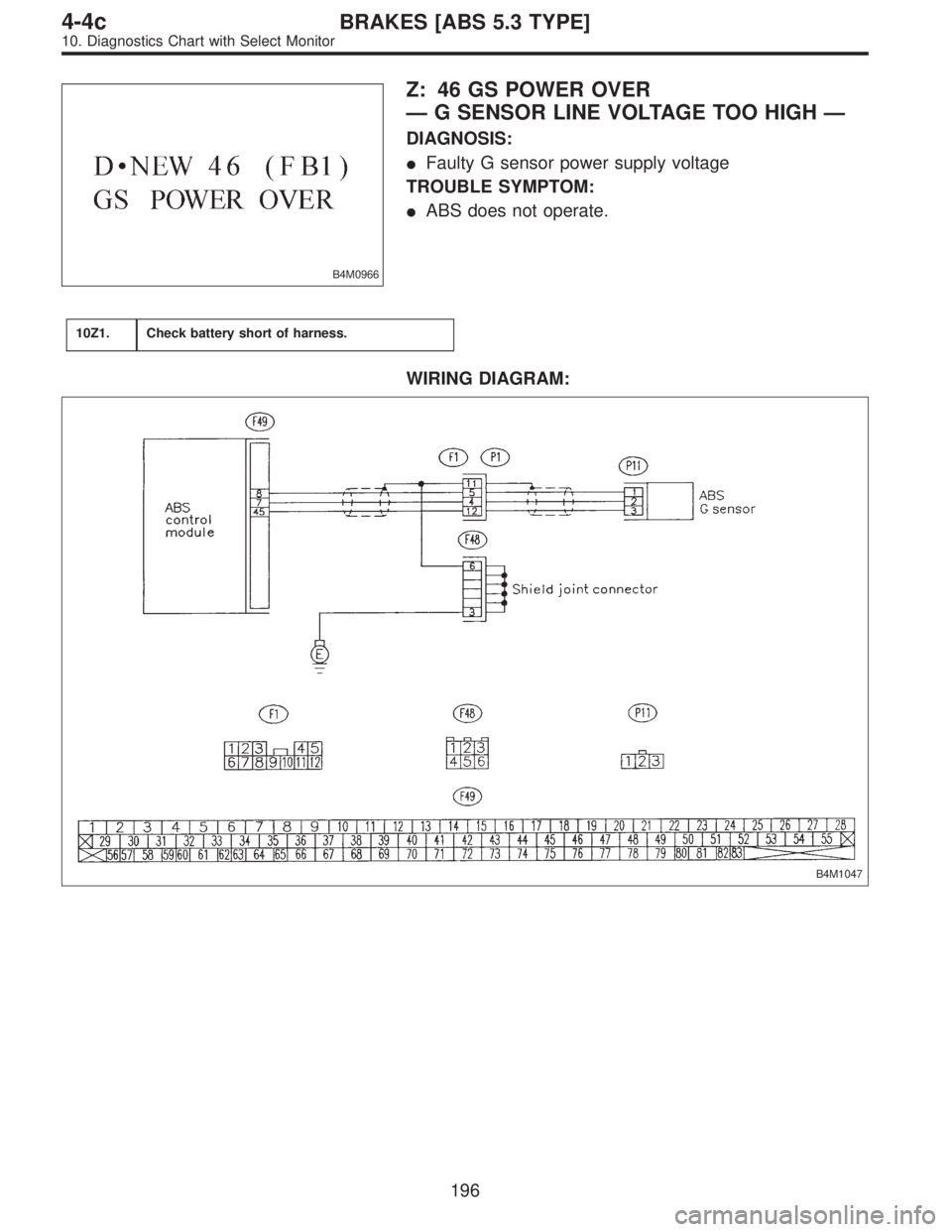
B4M0966
Z: 46 GS POWER OVER
—G SENSOR LINE VOLTAGE TOO HIGH—
DIAGNOSIS:
�Faulty G sensor power supply voltage
TROUBLE SYMPTOM:
�ABS does not operate.
10Z1.Check battery short of harness.
WIRING DIAGRAM:
B4M1047
196
4-4cBRAKES [ABS 5.3 TYPE]
10. Diagnostics Chart with Select Monitor
Page 2802 of 3342
B4M0855A
10Z1
CHECK BATTERY SHORT OF HARNESS.
1) Turn ignition switch to OFF.
2) Remove console cover from console box.
3) Disconnect connector from G sensor.
4) Disconnect connector from ABSCM.
5) Turn ignition switch to ON.
6) Measure voltage between ABSCM connector and chas-
sis ground.
: Connector & terminal
(F49) No. 8 (+)—Chassis ground (�)
(F49) No. 45 (+)—Chassis ground (�)
Is voltage 0 V?
: Go to next step.
: Repair harness between ABSCM and G sensor.
7) Turn ignition switch to OFF.
8) Measure voltage between ABSCM and chassis ground.
: Connector & terminal
(F49) No. 8 (+)—Chassis ground (�)
(F49) No. 45 (+)—Chassis ground (�)
Is voltage 0 V?
: Replace ABSCM.
: Repair harness between ABSCM and chassis
ground.
197
4-4cBRAKES [ABS 5.3 TYPE]
10. Diagnostics Chart with Select Monitor


 Measure hub runout.
: Is the runout less than 0.05 mm (0.")
 Turn ignition switch to OFF.
2) Disconnect connector from ABSCM.
3) Measure resistance between ABSCM and chassis
ground.
: Connector & terminal
(F49) No")
 Turn ignition switch to OFF.
2) Remove console cover from console box.
3) Disconnect connector from G sensor.
4) Disconnect connector from ABSCM.
5) Tu")