Page 2869 of 3342
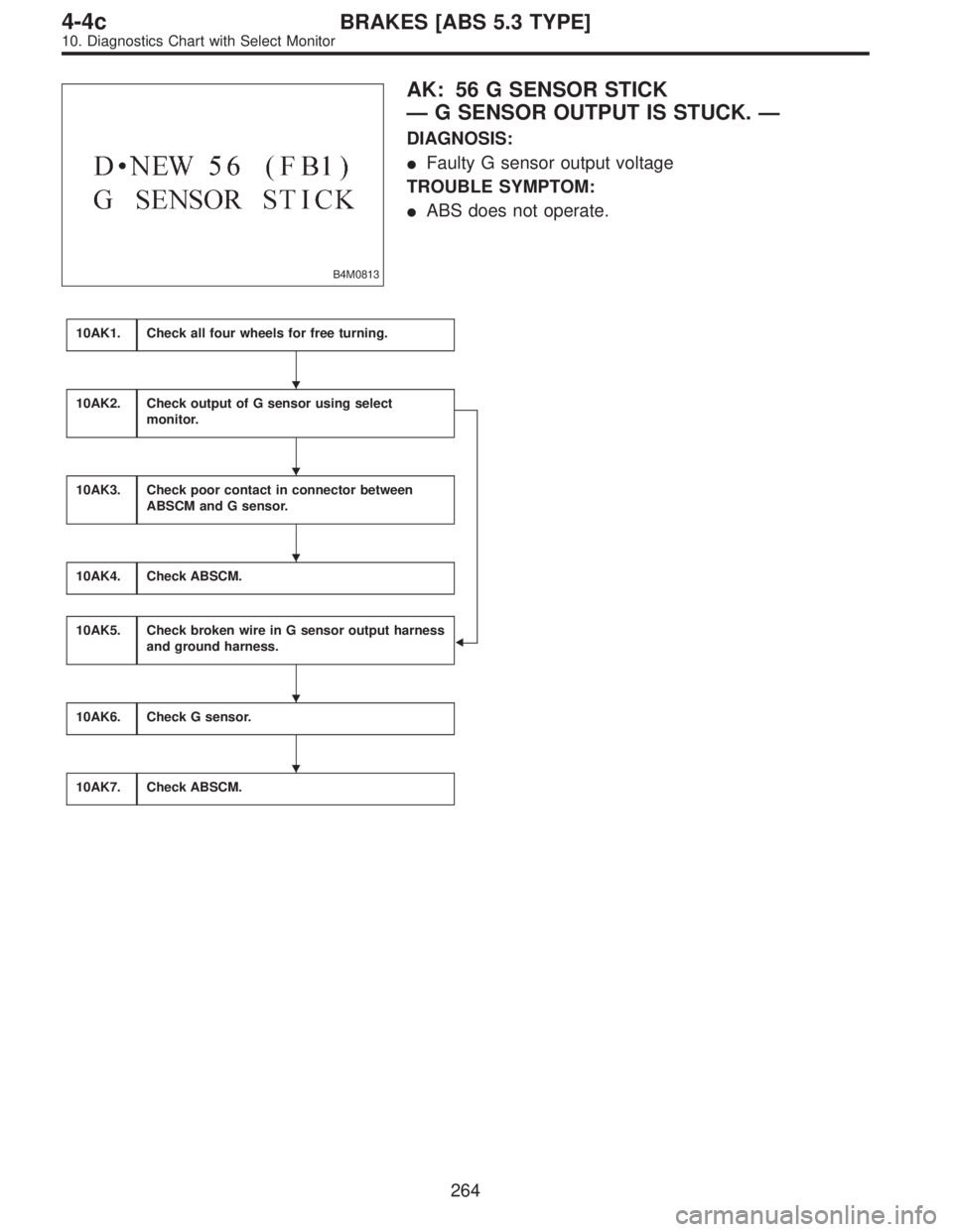
B4M0813
AK: 56 G SENSOR STICK
—G SENSOR OUTPUT IS STUCK.—
DIAGNOSIS:
�Faulty G sensor output voltage
TROUBLE SYMPTOM:
�ABS does not operate.
10AK1.Check all four wheels for free turning.
10AK2.Check output of G sensor using select
monitor.
�
10AK3.Check poor contact in connector between
ABSCM and G sensor.
10AK4.Check ABSCM.
10AK5.Check broken wire in G sensor output harness
and ground harness.
10AK6.Check G sensor.
10AK7.Check ABSCM.
�
�
�
�
�
264
4-4cBRAKES [ABS 5.3 TYPE]
10. Diagnostics Chart with Select Monitor
Page 2870 of 3342
WIRING DIAGRAM:
B4M1050
10AK1CHECK ALL FOUR WHEELS FOR FREE
TURNING.
: Have the wheels been turned freely such as
when the vehicle is lifted up, or operated on
a rolling road?
: The ABS is normal. Erase the trouble code.
: Go to step10AK2.
B4M0927
10AK2CHECK OUTPUT OF G SENSOR USING
SELECT MONITOR.
1) Press
F,
1and
0on the select monitor.
2) Read the select monitor display.
: Is the indicated reading 2.3±0.2 V when the
vehicle is in horizontal position?
: Go to next step.
: Go to step10AK5.
265
4-4cBRAKES [ABS 5.3 TYPE]
10. Diagnostics Chart with Select Monitor
Page 2871 of 3342
3) Remove console box.
4) Remove G sensor from vehicle. (Do not disconnect
connector.)
B4M0917A
5) Read the select monitor display.
: Is the indicated reading 3.9±0.2 V when G
sensor is inclined forwards to 90°?
: Go to next.
: Replace G sensor.
B4M0918A
: Is the indicated reading 0.7±0.2 V when G
sensor is inclined backwards to 90°?
: Go to step10AK3.
: Replace G sensor.
10AK3CHECK POOR CONTACT IN CONNEC-
TOR BETWEEN ABSCM AND G SENSOR.
: Is there poor contact in connector between
ABSCM and G sensor?
: Repair connector.
: Go to step10AK4.
266
4-4cBRAKES [ABS 5.3 TYPE]
10. Diagnostics Chart with Select Monitor
Page 2872 of 3342
10AK4
CHECK ABSCM.
1) Connect all connectors.
2) Erase the memory.
3) Perform inspection mode.
4) Read out the trouble code.
: Is the same trouble code as in the current
diagnosis still being output?
: Replace ABSCM.
: Go to next.
: Are other trouble codes being output?
: Proceed with the diagnosis corresponding to the
trouble code.
: A temporary poor contact.
B4M0912A
10AK5CHECK BROKEN WIRE IN G SENSOR
OUTPUT HARNESS AND GROUND HAR-
NESS.
1) Turn ignition switch to OFF.
2) Disconnect connector from ABSCM.
3) Measure resistance between ABSCM connector termi-
nals.
: Connector & terminal
(F49) No. 7—No. 45
Is resistance 4.6±0.3 kΩ?
: Go to step10AK6.
: Repair harness between G sensor and ABSCM.
267
4-4cBRAKES [ABS 5.3 TYPE]
10. Diagnostics Chart with Select Monitor
Page 2873 of 3342
B4M0915
10AK6
CHECK G SENSOR.
1) Remove console box.
2) Remove G sensor from vehicle.
3) Connect connector to G sensor.
4) Connect connector to ABSCM.
5) Turn ignition switch to ON.
6) Measure voltage between G sensor connector termi-
nals.
: Connector & terminal
(P11) No. 2 (+)—No.1(�)
Is voltage 2.3±0.2 V when G sensor is hori-
zontal?
: Go to next.
: Replace G sensor.
B4M0917A
: Connector & terminal
(P11) No. 2 (+)—No.1(�)
Is voltage 3.9±0.2 V when G sensor is
inclined forwards to 90°?
: Go to next.
: Replace G sensor.
B4M0918A
: Connector & terminal
(P11) No. 2 (+)—No.1(�)
Is voltage 0.7±0.2 V when G sensor is
inclined backwards to 90°?
: Go to step10AK7.
: Replace G sensor.
268
4-4cBRAKES [ABS 5.3 TYPE]
10. Diagnostics Chart with Select Monitor
Page 2875 of 3342

�ABS s")
11. General Diagnostics Table
A: SYMPTOMS AND PROBABLE CAUSES
Symptom Probable faulty units/parts
Vehicle instability during brakingVehicle pulls to either side.�Hydraulic unit (solenoid valve)
�ABS sensor
�Brake (caliper & piston, pads)
�Wheel alignment
�Tire specifications, tire wear and air pressures
�Incorrect wiring or piping connections
�Road surface (uneven, camber)
Vehicle spins.�Hydraulic unit (solenoid valve)
�ABS sensor
�Brake (pads)
�Tire specifications, tire wear and air pressures
�Incorrect wiring or piping connections
Poor brakingLong braking/stopping distance�Hydraulic unit (solenoid valve)
�Brake (pads)
�Air in brake line
�Tire specifications, tire wear and air pressures
�Incorrect wiring or piping connections
Wheel locks.�Hydraulic unit (solenoid valve, motor)
�ABS sensor
�Incorrect wiring or piping connections
Brake dragging�Hydraulic unit (solenoid valve)
�ABS sensor
�Master cylinder
�Brake (caliper & piston)
�Parking brake
�Axle & wheels
�Brake pedal play
Long brake pedal stroke�Air in brake line
�Brake pedal play
Vehicle pitching�Suspension play or fatigue (reduced damping)
�Incorrect wiring or piping connections
�Road surface (uneven)
Unstable or uneven braking�Hydraulic unit (solenoid valve)
�ABS sensor
�Brake (caliper & piston, pads)
�Tire specifications, tire wear and air pressures
�Incorrect wiring or piping connections
�Road surface (uneven)
Vibration and/or noise (while
driving on slippery roads)Excessive pedal vibration�Incorrect wiring or piping connections
�Road surface (uneven)
Noise from hydraulic unit�Hydraulic unit (mount bushing)
�ABS sensor
�Brake piping
Noise from front of vehicle�Hydraulic unit (mount bushing)
�ABS sensor
�Master cylinder
�Brake (caliper & piston, pads, rotor)
�Brake piping
�Brake booster & check valve
�Suspension play or fatigue
Noise from rear of vehicle�ABS sensor
�Brake (caliper & piston, pads, rotor)
�Parking brake
�Brake piping
�Suspension play or fatigue
270
4-4cBRAKES [ABS 5.3 TYPE]
11. General Diagnostics Table
Page 2877 of 3342

1. Supplemental Restraint System
“Airbag”
Airbag system wiring harness is routed near the ABS
sensor, ABS control module and hydraulic control unit.
CAUTION:
�All Airbag system wiring harness and connectors
are colored yellow. Do not use electrical test equip-
ment on these circuit.
�Be careful not to damage Airbag system wiring har-
ness when servicing the ABS sensor, ABS control
module and hydraulic control unit.
2. Pre-inspection
Before performing diagnostics, check the following items
which might affect ABS problems:
A: MECHANICAL INSPECTION
1. POWER SUPPLY
1) Measure battery voltage and specific gravity of electro-
lyte.
Standard voltage: 12 V, or more
Specific gravity: Above 1.260
2) Check the condition of the main and other fuses, and
harnesses and connectors. Also check for proper ground-
ing.
2. BRAKE FLUID
1) Check brake fluid level.
2) Check brake fluid leakage.
3. BRAKE DRAG
Check brake drag.
4. BRAKE PAD AND ROTOR
Check brake pad and rotor.
5. TIRE SPECIFICATIONS, TIRE WEAR AND AIR
PRESSURE
Check tire specifications, tire wear and air pressure.
to 4-2 [S1A1], 4-2 [S1A2].>
2
4-4dBRAKES [ABS 5.3i TYPE]
1. Supplemental Restraint System“Airbag”- 2. Pre-inspection
Page 2878 of 3342

1. Supplemental Restraint System
“Airbag”
Airbag system wiring harness is routed near the ABS
sensor, ABS control module and hydraulic control unit.
CAUTION:
�All Airbag system wiring harness and connectors
are colored yellow. Do not use electrical test equip-
ment on these circuit.
�Be careful not to damage Airbag system wiring har-
ness when servicing the ABS sensor, ABS control
module and hydraulic control unit.
2. Pre-inspection
Before performing diagnostics, check the following items
which might affect ABS problems:
A: MECHANICAL INSPECTION
1. POWER SUPPLY
1) Measure battery voltage and specific gravity of electro-
lyte.
Standard voltage: 12 V, or more
Specific gravity: Above 1.260
2) Check the condition of the main and other fuses, and
harnesses and connectors. Also check for proper ground-
ing.
2. BRAKE FLUID
1) Check brake fluid level.
2) Check brake fluid leakage.
3. BRAKE DRAG
Check brake drag.
4. BRAKE PAD AND ROTOR
Check brake pad and rotor.
5. TIRE SPECIFICATIONS, TIRE WEAR AND AIR
PRESSURE
Check tire specifications, tire wear and air pressure.
to 4-2 [S1A1], 4-2 [S1A2].>
2
4-4dBRAKES [ABS 5.3i TYPE]
1. Supplemental Restraint System“Airbag”- 2. Pre-inspection

 Remove console box.
4) Remove G sensor from vehicle. (Do not disconnect
connector.)
B4M0917A
5) Read the select monitor display.
: Is the indicated reading 3.9±0.2 V when G
sensor is inclined forw")
 Connect all connectors.
2) Erase the memory.
3) Perform inspection mode.
4) Read out the trouble code.
: Is the same trouble code as in the current
diagnosis still being output?")
 Remove console box.
2) Remove G sensor from vehicle.
3) Connect connector to G sensor.
4) Connect connector to ABSCM.
5) Turn ignition switch to ON.
6) Measure voltage")