Page 2908 of 3342
8E8CHECK INSTALLATION OF TONE
WHEEL.
Tightening torque:
13±3 N⋅m (1.3±0.3 kg-m, 9±2.2 ft-lb)
: Are the tone wheel installation bolts tight-
ened securely?
: Go to step8E9.
: Tighten tone wheel installation bolts securely.
G4M0700
8E9
CHECK ABS SENSOR GAP.
Measure tone wheel-to-pole piece gap over entire perim-
eter of the wheel.
: Is the gap within the specifications shown
in the following table?
SpecificationsFront wheel Rear wheel
0.9—1.4 mm
(0.035—0.055 in)0.7—1.2 mm
(0.028—0.047 in)
G4M0701
: Go to step8E10.
: Adjust the gap.
NOTE:
Adjust the gap using spacers (Part No. 26755AA000). If
spacers cannot correct the gap, replace worn sensor or
worn tone wheel.
8E10
CHECK HUB RUNOUT.
Measure hub runout.
: Is the runout less than 0.05 mm (0.0020 in)?
: Go to step8E11.
: Repair hub.
32
4-4dBRAKES [ABS 5.3i TYPE]
8. Diagnostics Chart with Trouble Code by ABS Warning Light
Page 2909 of 3342
 Turn ignition switch to ON.
2) Measure resistance between ABS sensor and chassis
ground.
Terminal
Front RH No. 1—Chassis ground:
Front LH")
B4M0818E
B4M1042C
8E11CHECK GROUND SHORT OF ABS SEN-
SOR.
1) Turn ignition switch to ON.
2) Measure resistance between ABS sensor and chassis
ground.
Terminal
Front RH No. 1—Chassis ground:
Front LH No. 1—Chassis ground:
Rear RH No. 1—Chassis ground:
Rear LH No. 1—Chassis ground:
: Is the resistance more than 1 MΩ?
: Go to step8E12.
: Replace ABS sensor and ABSCM&H/U.
B4M1241A
8E12
CHECK GROUND SHORT OF HARNESS.
1) Turn ignition switch to OFF.
2) Connect connector to ABS sensor.
3) Measure resistance between ABSCM&H/U connector
terminal and chassis ground.
Connector & terminal
Trouble code 21 / (F49) No. 11—Chassis ground:
Trouble code 23 / (F49) No. 9—Chassis ground:
Trouble code 25 / (F49) No. 14—Chassis ground:
Trouble code 27 / (F49) No. 7—Chassis ground:
: Is the resistance more than 1 MΩ?
: Go to step8E13.
: Repair harness between ABSCM&H/U and ABS
sensor.
Replace ABSCM&H/U.
8E13CHECK POOR CONTACT IN CONNEC-
TORS.
: Is there poor contact in connectors between
ABSCM&H/U and ABS sensor?
FOREWORD [T3C1].>
: Repair connector.
: Go to step8E14.
33
4-4dBRAKES [ABS 5.3i TYPE]
8. Diagnostics Chart with Trouble Code by ABS Warning Light
Page 2910 of 3342
8E14
CHECK ABSCM&H/U.
1) Connect all connectors.
2) Erase the memory.
3) Perform inspection mode.
4) Read out the trouble code.
: Is the same trouble code as in the current
diagnosis still being output?
: Replace ABSCM&H/U.
: Go to step8E15.
8E15CHECK ANY OTHER TROUBLE CODES
APPEARANCE.
: Are other trouble codes being output?
: Proceed with the diagnosis corresponding to the
trouble code.
: A temporary poor contact.
NOTE:
Check harness and connectors between ABSCM&H/U and
ABS sensor.
34
4-4dBRAKES [ABS 5.3i TYPE]
8. Diagnostics Chart with Trouble Code by ABS Warning Light
Page 2911 of 3342
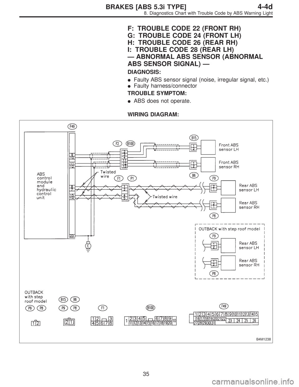
F: TROUBLE CODE 22 (FRONT RH)
G: TROUBLE CODE 24 (FRONT LH)
H: TROUBLE CODE 26 (REAR RH)
I: TROUBLE CODE 28 (REAR LH)
—ABNORMAL ABS SENSOR (ABNORMAL
ABS SENSOR SIGNAL)—
DIAGNOSIS:
�Faulty ABS sensor signal (noise, irregular signal, etc.)
�Faulty harness/connector
TROUBLE SYMPTOM:
�ABS does not operate.
WIRING DIAGRAM:
B4M1238
35
4-4dBRAKES [ABS 5.3i TYPE]
8. Diagnostics Chart with Trouble Code by ABS Warning Light
Page 2912 of 3342

: Are the ABS sensor installation bolts tight-
ened securely?
: Go to step8I2.
: Tighten ABS sensor")
8I1CHECK INSTALLATION OF ABS SEN-
SOR.
Tightening torque:
32±10 N⋅m (3.3±1.0 kg-m, 24±7 ft-lb)
: Are the ABS sensor installation bolts tight-
ened securely?
: Go to step8I2.
: Tighten ABS sensor installation bolts securely.
8I2CHECK INSTALLATION OF TONE
WHEEL.
Tightening torque:
13±3 N⋅m (1.3±0.3 kg-m, 9±2.2 ft-lb)
: Are the tone wheel installation bolts tight-
ened securely?
: Go to step8I3.
: Tighten tone wheel installation bolts securely.
G4M0700
8I3
CHECK ABS SENSOR GAP.
Measure tone wheel to pole piece gap over entire perim-
eter of the wheel.
: Is the gap within the specifications shown
in the following table?
SpecificationsFront wheel Rear wheel
0.9—1.4 mm
(0.035—0.055 in)0.7—1.2 mm
(0.028—0.047 in)
G4M0701
: Go to step8I4.
: Adjust the gap.
NOTE:
Adjust the gap using spacer (Part No. 26755AA000). If
spacers cannot correct the gap, replace worn sensor or
worn tone wheel.
8I4
CHECK OSCILLOSCOPE.
: Is an oscilloscope available?
: Go to step8I5.
: Go to step8I6.
36
4-4dBRAKES [ABS 5.3i TYPE]
8. Diagnostics Chart with Trouble Code by ABS Warning Light
Page 2913 of 3342
 Raise all four wheels of ground.
2) Turn ignition switch OFF.
3) Connect the oscilloscope to the connector (F1) or con-
nector (B100).
4) Turn ignition switch ON.
B4M12")
8I5
CHECK ABS SENSOR SIGNAL.
1) Raise all four wheels of ground.
2) Turn ignition switch OFF.
3) Connect the oscilloscope to the connector (F1) or con-
nector (B100).
4) Turn ignition switch ON.
B4M1242A
5) Rotate wheels and measure voltage at specified fre-
quency.
NOTE:
When this inspection is completed, the ABS control mod-
ule sometimes stores the trouble code 29.
Connector & terminal
Trouble code 22 / (B100) No. 12 (+)—No. 13 (�):
Trouble code 24 / (B100) No. 3 (+)—No.4(�):
Trouble code 26 / (F1) No. 4 (+)—No.5(�):
Trouble code 28 / (F1) No. 1 (+)—No.2(�):
Specified voltage: 0.12—1 V (When it is 20 Hz.)
: Is oscilloscope pattern smooth, as shown in
figure?
: Go to step8I9.
: Go to step8I6.
8I6CHECK CONTAMINATION OF ABS SEN-
SOR OR TONE WHEEL.
Remove disc rotor or drum from hub in accordance with
trouble code.
: Is the ABS sensor pole piece or the tone
wheel contaminated by dirt or other foreign
matter?
: Thoroughly remove dirt or other foreign matter.
: Go to step8I7.
8I7CHECK DAMAGE OF ABS SENSOR OR
TONE WHEEL.
: Are there broken or damaged in the ABS
sensor pole piece or the tone wheel?
: Replace ABS sensor or tone wheel.
: Go to step8I8.
37
4-4dBRAKES [ABS 5.3i TYPE]
8. Diagnostics Chart with Trouble Code by ABS Warning Light
Page 2914 of 3342
8I8
CHECK HUB RUNOUT.
Measure hub runout.
: Is the runout less than 0.05 mm (0.0020 in)?
: Go to step8I9.
: Repair hub.
B4M0806E
B4M1036C
8I9
CHECK RESISTANCE OF ABS SENSOR.
1) Turn ignition switch OFF.
2) Disconnect connector from ABS sensor.
3) Measure resistance between ABS sensor connector ter-
minals.
Terminal
Front RH No. 1—No. 2:
Front LH No. 1—No. 2:
Rear RH No. 1—No. 2:
Rear LH No. 1—No. 2:
: Is the resistance between 0.8 and 1.2 kΩ?
: Go to step8I10.
: Replace ABS sensor.
B4M0818E
B4M1042C
8I10CHECK GROUND SHORT OF ABS SEN-
SOR.
Measure resistance between ABS sensor and chassis
ground.
Terminal
Front RH No. 1—Chassis ground:
Front LH No. 1—Chassis ground:
Rear RH No. 1—Chassis ground:
Rear LH No. 1—Chassis ground:
: Is the resistance more than 1 MΩ?
: Go to step8I11.
: Replace ABS sensor.
38
4-4dBRAKES [ABS 5.3i TYPE]
8. Diagnostics Chart with Trouble Code by ABS Warning Light
Page 2915 of 3342
 Connect connector to ABS sensor.
2) Disconnect connector from ABSCM&H/U.
3) Measure resistance at ABSCM&H/U connector termi-
nals.")
B4M1239A
8I11CHECK HARNESS/CONNECTOR
BETWEEN ABSCM AND ABS SENSOR.
1) Connect connector to ABS sensor.
2) Disconnect connector from ABSCM&H/U.
3) Measure resistance at ABSCM&H/U connector termi-
nals.
Connector & terminal
Trouble code 22 / (F49) No. 11—No. 12:
Trouble code 24 / (F49) No. 9—No. 10:
Trouble code 26 / (F49) No. 14—No. 15:
Trouble code 28 / (F49) No. 7—No. 8:
: Is the resistance between 0.8 and 1.2 kΩ?
: Go to step8I12.
: Repair harness/connector between ABSCM&H/U
and ABS sensor.
B4M1241A
8I12
CHECK GROUND SHORT OF HARNESS.
Measure resistance between ABSCM&H/U connector and
chassis ground.
Connector & terminal
Trouble code 22 / (F49) No. 11—Chassis ground:
Trouble code 24 / (F49) No. 9—Chassis ground:
Trouble code 26 / (F49) No. 14—Chassis ground:
Trouble code 28 / (F49) No. 7—Chassis ground:
: Is the resistance more than 1 MΩ?
: Go to step8I13.
: Repair harness/connector between ABSCM&H/U
and ABS sensor.
B4M1243A
8I13CHECK GROUND CIRCUIT OF
ABSCM&H/U.
Measure resistance between ABSCM&H/U and chassis
ground.
Connector & terminal
(F49) No. 23—GND:
: Is the resistance less than 0.5Ω?
: Go to step8I14.
: Repair ABSCM&H/U ground harness.
39
4-4dBRAKES [ABS 5.3i TYPE]
8. Diagnostics Chart with Trouble Code by ABS Warning Light

: Are the tone wheel installation bolts tight-
ened securely?
: Go to step8E9.
: Tighten tone wheel in")
 Connect all connectors.
2) Erase the memory.
3) Perform inspection mode.
4) Read out the trouble code.
: Is the same trouble code as in the current
diagnosis still being outpu")
?
: Go to step8I9.
: Repair hub.
B4M0806E
B4M1036C
8I9
CHECK RESISTANCE OF ABS SENSOR.
1) Turn ignition switch OF")