Page 2983 of 3342
 Turn ignition switch to ON.
2) Measure resistance between ABS sensor and chassis
ground.
Terminal
Front RH No. 1—Chassis ground:
Front L")
B4M0818E
B4M1042C
10H19CHECK GROUND SHORT OF ABS SEN-
SOR.
1) Turn ignition switch to ON.
2) Measure resistance between ABS sensor and chassis
ground.
Terminal
Front RH No. 1—Chassis ground:
Front LH No. 1—Chassis ground:
Rear RH No. 1—Chassis ground:
Rear LH No. 1—Chassis ground:
: Is the resistance more than 1 MΩ?
: Go to step10H20.
: Replace ABS sensor and ABSCM&H/U.
B4M1241A
10H20
CHECK GROUND SHORT OF HARNESS.
1) Turn ignition switch to OFF.
2) Connect connector to ABS sensor.
3) Measure resistance between ABSCM&H/U connector
terminal and chassis ground.
Connector & terminal
Trouble code 21 / (F49) No. 11—Chassis ground:
Trouble code 23 / (F49) No. 9—Chassis ground:
Trouble code 25 / (F49) No. 14—Chassis ground:
Trouble code 27 / (F49) No. 7—Chassis ground:
: Is the resistance more than 1 MΩ?
: Go to step10H21.
: Repair harness between ABSCM&H/U and ABS
sensor.
And replace ABSCM&H/U.
10H21CHECK POOR CONTACT IN CONNEC-
TORS.
: Is there poor contact in connectors between
ABSCM&H/U and ABS sensor?
FOREWORD [T3C1].>
: Repair connector.
: Go to step10H22.
107
4-4dBRAKES [ABS 5.3i TYPE]
10. Diagnostics Chart with Select Monitor
Page 2984 of 3342
10H22
CHECK ABSCM&H/U.
1) Connect all connectors.
2) Erase the memory.
3) Perform inspection mode.
4) Read out the trouble code.
: Is the same trouble code as in the current
diagnosis still being output?
: Replace ABSCM&H/U.
: Go to step10H23.
10H23CHECK ANY OTHER TROUBLE CODES
APPEARANCE.
: Are other trouble codes being output?
: Proceed with the diagnosis corresponding to the
trouble code.
: A temporary poor contact.
NOTE:
Check harness and connectors between ABSCM&H/U and
ABS sensor.
108
4-4dBRAKES [ABS 5.3i TYPE]
10. Diagnostics Chart with Select Monitor
Page 2985 of 3342
B4M0812
I: TROUBLE CODE 22 FR. SS SOFT
—ABNORMAL FRONT RH ABS SENSOR
(ABNORMAL ABS SENSOR SIGNAL)—
B4M0949
J: TROUBLE CODE 24 FL. SS SOFT
—ABNORMAL FRONT LH ABS SENSOR
(ABNORMAL ABS SENSOR SIGNAL)—
B4M0950
K: TROUBLE CODE 26 RR. SS SOFT
—ABNORMAL REAR RH ABS SENSOR
(ABNORMAL ABS SENSOR SIGNAL)—
B4M0951
L: TROUBLE CODE 28 RL. SS SOFT
—ABNORMAL REAR LH ABS SENSOR
(ABNORMAL ABS SENSOR SIGNAL)—
109
4-4dBRAKES [ABS 5.3i TYPE]
10. Diagnostics Chart with Select Monitor
Page 2986 of 3342
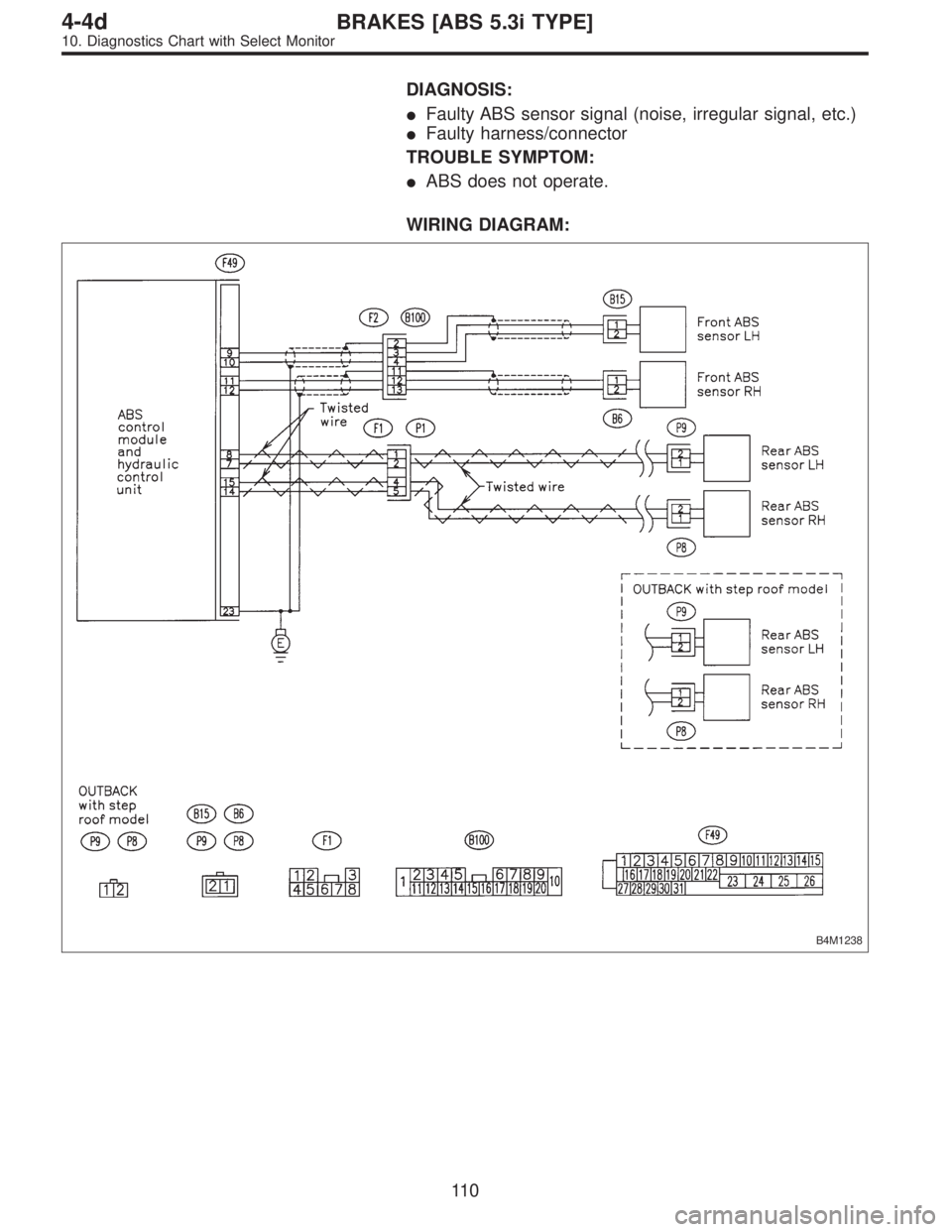
DIAGNOSIS:
�Faulty ABS sensor signal (noise, irregular signal, etc.)
�Faulty harness/connector
TROUBLE SYMPTOM:
�ABS does not operate.
WIRING DIAGRAM:
B4M1238
11 0
4-4dBRAKES [ABS 5.3i TYPE]
10. Diagnostics Chart with Select Monitor
Page 2987 of 3342

B4M0922
10L1CHECK OUTPUT OF ABS SENSOR
USING SELECT MONITOR.
Read the ABS sensor output corresponding to the faulty
system in the select monitor function mode.
NOTE:
The select monitor display shows that the front right wheel
is rotating at 30 km/h.
: Does the speed indicated on the display
change in response to the speedometer
reading during acceleration/deceleration
when the steering wheel is in the straight-
ahead position?
: Go to step10L2.
: Go to step10L8.
10L2CHECK POOR CONTACT IN CONNEC-
TORS.
Turn ignition switch to OFF.
: Is there poor contact in connectors between
ABSCM&H/U and ABS sensor?
: Repair connector.
: Go to step10L3.
10L3
CHECK SOURCES OF SIGNAL NOISE.
: Is the car telephone or the wireless trans-
mitter properly installed?
: Go to step10L4.
: Properly install the car telephone or the wireless
transmitter.
10L4
CHECK SOURCES OF SIGNAL NOISE.
: Are noise sources (such as an antenna)
installed near the sensor harness?
: Install the noise sources apart from the sensor
harness.
: Go to step10L5.
111
4-4dBRAKES [ABS 5.3i TYPE]
10. Diagnostics Chart with Select Monitor
Page 2988 of 3342
 Turn ignition switch to OFF.
2) Connect all connectors.
3) Measure resistance between shield connector and
chassis ground.
Connector & terminal
Trouble code 22 /")
B4M1244A
10L5
CHECK SHIELD CIRCUIT.
1) Turn ignition switch to OFF.
2) Connect all connectors.
3) Measure resistance between shield connector and
chassis ground.
Connector & terminal
Trouble code 22 / (B100) No. 11—Chassis ground:
Trouble code 24 / (B100) No. 2—Chassis ground:
Trouble code 26 / Go to step 10L6.
Trouble code 28 / Go to step 10L6.
: Is the resistance less than 0.5Ω?
: Go to step10L6.
: Repair shield harness.
10L6
CHECK ABSCM&H/U.
1) Connect all connectors.
2) Erase the memory.
3) Perform inspection mode.
4) Read out the trouble code.
: Is the same trouble code as in the current
diagnosis still being output?
: Replace ABSCM&H/U.
: Go to step10L7.
10L7CHECK ANY OTHER TROUBLE CODES
APPEARANCE.
: Are other trouble codes being output?
: Proceed with the diagnosis corresponding to the
trouble code.
: A temporary noise interference.
10L8CHECK INSTALLATION OF ABS SEN-
SOR.
Tightening torque:
32±10 N⋅m (3.3±1.0 kg-m, 24±7 ft-lb)
: Are the ABS sensor installation bolts tight-
ened securely?
: Go to step10L9.
: Tighten ABS sensor installation bolts securely.
11 2
4-4dBRAKES [ABS 5.3i TYPE]
10. Diagnostics Chart with Select Monitor
Page 2989 of 3342

: Are the tone wheel installation bolts tight-
ened securely?
: Go to step10L10.
: Tighten tone wheel")
10L9CHECK INSTALLATION OF TONE
WHEEL.
Tightening torque:
13±3 N⋅m (1.3±0.3 kg-m, 9±2.2 ft-lb)
: Are the tone wheel installation bolts tight-
ened securely?
: Go to step10L10.
: Tighten tone wheel installation bolts securely.
G4M0700
10L10
CHECK ABS SENSOR GAP.
Measure tone wheel to pole piece gap over entire perim-
eter of the wheel.
: Is the gap within the specifications shown
in the following table?
SpecificationsFront wheel Rear wheel
0.9—1.4 mm
(0.035—0.055 in)0.7—1.2 mm
(0.028—0.047 in)
G4M0701
: Go to step10L11.
: Adjust the gap.
NOTE:
Adjust the gap using spacer (Part No. 26755AA000). If
spacers cannot correct the gap, replace worn sensor or
worn tone wheel.
10L11
CHECK OSCILLOSCOPE.
: Is an oscilloscope available?
: Go to step10L12.
: Go to step10L13.
10L12
CHECK ABS SENSOR SIGNAL.
1) Raise all four wheels of ground.
2) Turn ignition switch OFF.
3) Connect the oscilloscope to the connector (F1) or con-
nector (B100) in accordance with trouble code.
4) Turn ignition switch ON.
11 3
4-4dBRAKES [ABS 5.3i TYPE]
10. Diagnostics Chart with Select Monitor
Page 2990 of 3342
 Rotate wheels and measure voltage at specified fre-
quency.
NOTE:
When this inspection is completed, the ABSCM&H/U
sometimes stores the trouble code 29.
Connector & terminal
Trouble code 2")
B4M1242A
5) Rotate wheels and measure voltage at specified fre-
quency.
NOTE:
When this inspection is completed, the ABSCM&H/U
sometimes stores the trouble code 29.
Connector & terminal
Trouble code 22 / (B100) No. 12 (+)—No. 13 (�):
Trouble code 24 / (B100) No. 3 (+)—No.4(�):
Trouble code 26 / (F1) No. 4 (+)—No.5(�):
Trouble code 28 / (F1) No. 1 (+)—No.2(�):
Specified voltage: 0.12—1 V (When it is 20 Hz.)
: Is oscilloscope pattern smooth, as shown in
figure?
: Go to step10L16.
: Go to step10L13.
10L13CHECK CONTAMINATION OF ABS SEN-
SOR OR TONE WHEEL.
Remove disc rotor or drum from hub in accordance with
trouble code.
: Is the ABS sensor pole piece or the tone
wheel contaminated by dirt or other foreign
matter?
: Thoroughly remove dirt or other foreign matter.
: Go to step10L14.
10L14CHECK DAMAGE OF ABS SENSOR OR
TONE WHEEL.
: Are there broken or damaged in the ABS
sensor pole piece or the tone wheel?
: Replace ABS sensor or tone wheel.
: Go to step10L15.
10L15
CHECK HUB RUNOUT.
Measure hub runout.
: Is the runout less than 0.05 mm (0.0020 in)?
: Go to step10L16.
: Repair hub.
11 4
4-4dBRAKES [ABS 5.3i TYPE]
10. Diagnostics Chart with Select Monitor
 Connect all connectors.
2) Erase the memory.
3) Perform inspection mode.
4) Read out the trouble code.
: Is the same trouble code as in the current
diagnosis still being outp")
—
B4M0949
J: TROUBLE CODE 24 FL. SS SOFT
—ABNORMAL FRONT LH ABS SENSOR
(ABNORMAL ABS SENSOR SIGNA")