Page 2991 of 3342
B4M0806E
B4M1036C
10L16
CHECK RESISTANCE OF ABS SENSOR.
1) Turn ignition switch OFF.
2) Disconnect connector from ABS sensor.
3) Measure resistance between ABS sensor connector ter-
minals.
Terminal
Front RH No. 1—No. 2:
Front LH No. 1—No. 2:
Rear RH No. 1—No. 2:
Rear LH No. 1—No. 2:
: Is the resistance between 0.8 and 1.2 kΩ?
: Go to step10L17.
: Replace ABS sensor.
B4M0818E
B4M1042C
10L17CHECK GROUND SHORT OF ABS SEN-
SOR.
Measure resistance between ABS sensor and chassis
ground.
Terminal
Front RH No. 1—Chassis ground:
Front LH No. 1—Chassis ground:
Rear RH No. 1—Chassis ground:
Rear LH No. 1—Chassis ground:
: Is the resistance more than 1 MΩ?
: Go to step10L18.
: Replace ABS sensor.
11 5
4-4dBRAKES [ABS 5.3i TYPE]
10. Diagnostics Chart with Select Monitor
Page 2992 of 3342
 Connect connector to ABS sensor.
2) Disconnect connector from ABSCM&H/U.
3) Measure resistance at ABSCM&H/U connector termi")
B4M1239A
10L18CHECK HARNESS/CONNECTOR
BETWEEN ABSCM&H/U AND ABS SEN-
SOR.
1) Connect connector to ABS sensor.
2) Disconnect connector from ABSCM&H/U.
3) Measure resistance at ABSCM&H/U connector termi-
nals.
Connector & terminal
Trouble code 22 / (F49) No. 11—No. 12:
Trouble code 24 / (F49) No. 9—No. 10:
Trouble code 26 / (F49) No. 14—No. 15:
Trouble code 28 / (F49) No. 7—No. 8:
: Is the resistance between 0.8 and 1.2 kΩ?
: Go to step10L19.
: Repair harness/connector between ABSCM&H/U
and ABS sensor.
B4M1241A
10L19
CHECK GROUND SHORT OF HARNESS.
Measure resistance between ABSCM&H/U connector and
chassis ground.
Connector & terminal
Trouble code 22 / (F49) No. 11—Chassis ground:
Trouble code 24 / (F49) No. 9—Chassis ground:
Trouble code 26 / (F49) No. 14—Chassis ground:
Trouble code 28 / (F49) No. 7—Chassis ground:
: Is the resistance more than 1 MΩ?
: Go to step10L20.
: Repair harness/connector between ABSCM&H/U
and ABS sensor.
B4M1243A
10L20CHECK GROUND CIRCUIT OF
ABSCM&H/U.
Measure resistance between ABSCM&H/U and chassis
ground.
Connector & terminal
(F49) No. 23—GND:
: Is the resistance less than 0.5Ω?
: Go to step10L21.
: Repair ABSCM&H/U ground harness.
11 6
4-4dBRAKES [ABS 5.3i TYPE]
10. Diagnostics Chart with Select Monitor
Page 2993 of 3342
![SUBARU LEGACY 1997 Service Repair Manual 10L21CHECK POOR CONTACT IN CONNEC-
TORS.
: Is there poor contact in connectors between
ABSCM&H/U and ABS sensor? <Ref. to
FOREWORD [T3C1].>
: Repair connector.
: Go to step10L22.
10L22
CHECK SOURCES O](/manual-img/17/57434/w960_57434-2992.png "SUBARU LEGACY 1997 Service Repair Manual 10L21CHECK POOR CONTACT IN CONNEC-
TORS.
: Is there poor contact in connectors between
ABSCM&H/U and ABS sensor? <Ref. to
FOREWORD [T3C1].>
: Repair connector.
: Go to step10L22.
10L22
CHECK SOURCES O")
10L21CHECK POOR CONTACT IN CONNEC-
TORS.
: Is there poor contact in connectors between
ABSCM&H/U and ABS sensor?
FOREWORD [T3C1].>
: Repair connector.
: Go to step10L22.
10L22
CHECK SOURCES OF SIGNAL NOISE.
: Is the car telephone or the wireless trans-
mitter properly installed?
: Go to step10L23.
: Properly install the car telephone or the wireless
transmitter.
10L23
CHECK SOURCES OF SIGNAL NOISE.
: Are noise sources (such as an antenna)
installed near the sensor harness?
: Install the noise sources apart from the sensor
harness.
: Go to step10L24.
B4M1244A
10L24
CHECK SHIELD CIRCUIT.
1) Connect all connectors.
2) Measure resistance between shield connector and
chassis ground.
Connector & terminal
Trouble code 22 / (B100) No. 11—Chassis ground:
Trouble code 24 / (B100) No. 2—Chassis ground:
Trouble code 26 / Go to step 10L25.
Trouble code 28 / Go to step 10L25.
: Is the resistance less than 0.5Ω?
: Go to step10L25.
: Repair shield harness.
11 7
4-4dBRAKES [ABS 5.3i TYPE]
10. Diagnostics Chart with Select Monitor
Page 2995 of 3342
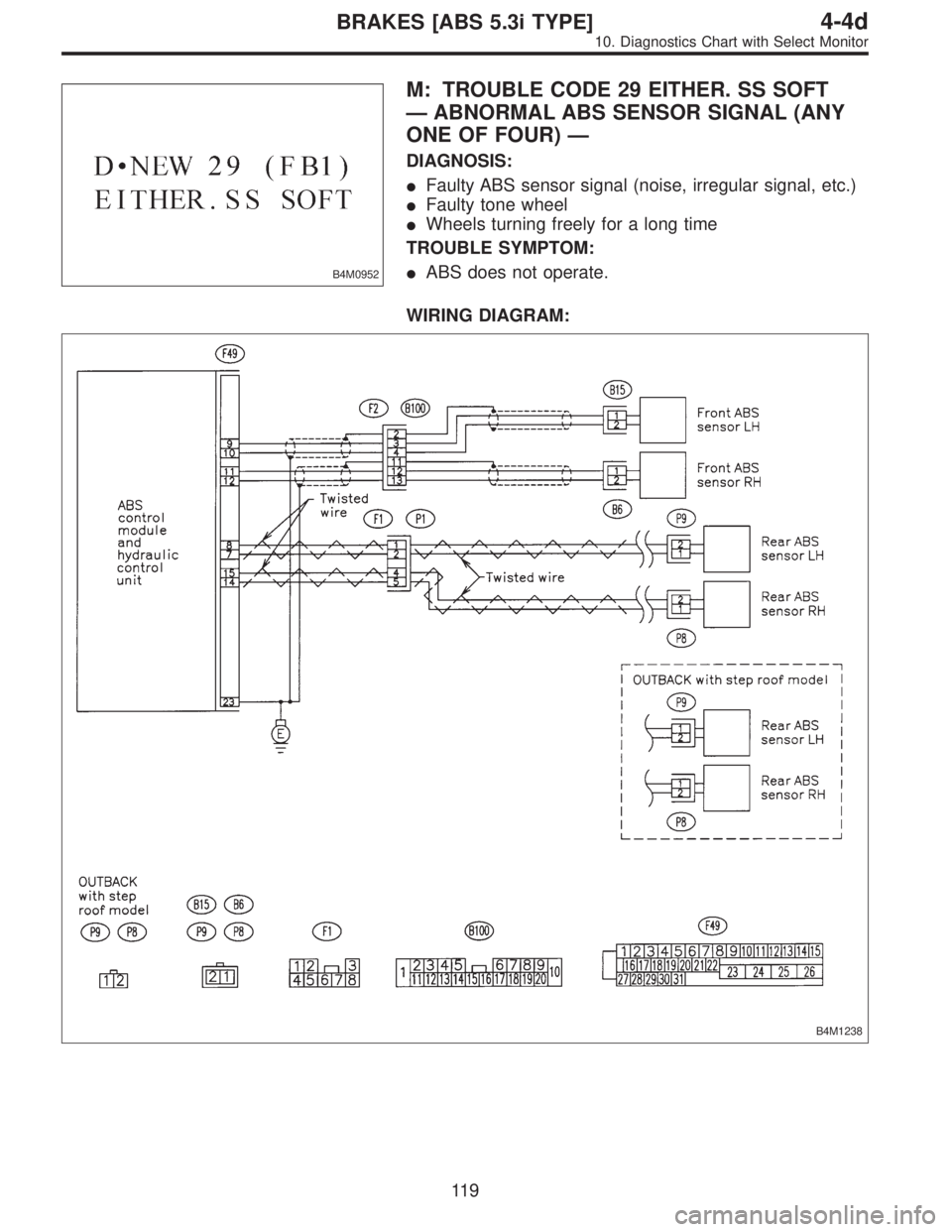
B4M0952
M: TROUBLE CODE 29 EITHER. SS SOFT
—ABNORMAL ABS SENSOR SIGNAL (ANY
ONE OF FOUR)—
DIAGNOSIS:
�Faulty ABS sensor signal (noise, irregular signal, etc.)
�Faulty tone wheel
�Wheels turning freely for a long time
TROUBLE SYMPTOM:
�ABS does not operate.
WIRING DIAGRAM:
B4M1238
11 9
4-4dBRAKES [ABS 5.3i TYPE]
10. Diagnostics Chart with Select Monitor
Page 2996 of 3342

10M1CHECK IF THE WHEELS HAVE TURNED
FREELY FOR A LONG TIME.
: Check if the wheels have been turned freely
for more than one minute, such as when the
vehicle is jacked-up, under full-lock corner-
ing or when tire is not in contact with road
surface.
: The ABS is normal. Erase the trouble code.
NOTE:
When the wheels turn freely for a long time, such as when
the vehicle is towed or jacked-up, or when steering wheel
is continuously turned all the way, this trouble code may
sometimes occur.
: Go to step10M2.
10M2
CHECK TIRE SPECIFICATIONS.
Turn ignition switch to OFF.
: Are the tire specifications correct?
: Go to step10M3.
: Replace tire.
10M3
CHECK WEAR OF TIRE.
: Is the tire worn excessively?
: Replace tire.
: Go to step10M4.
10M4
CHECK TIRE PRESSURE.
: Is the tire pressure correct?
: Go to step10M5.
: Adjust tire pressure.
10M5CHECK INSTALLATION OF ABS SEN-
SOR.
Tightening torque:
32±10 N⋅m (3.3±1.0 kg-m, 24±7 ft-lb)
: Are the ABS sensor installation bolts tight-
ened securely?
: Go to step10M6.
: Tighten ABS sensor installation bolts securely.
120
4-4dBRAKES [ABS 5.3i TYPE]
10. Diagnostics Chart with Select Monitor
Page 2997 of 3342

: Are the tone wheel installation bolts tight-
ened securely?
: Go to step10M7.
: Tighten tone wheel")
10M6CHECK INSTALLATION OF TONE
WHEEL.
Tightening torque:
13±3 N⋅m (1.3±0.3 kg-m, 9±2.2 ft-lb)
: Are the tone wheel installation bolts tight-
ened securely?
: Go to step10M7.
: Tighten tone wheel installation bolts securely.
G4M0700
10M7
CHECK ABS SENSOR GAP.
Measure tone wheel to pole piece gap over entire perim-
eter of the wheel.
: Is the gap within the specifications shown
in the following table?
SpecificationsFront wheel Rear wheel
0.9—1.4 mm
(0.035—0.055 in)0.7—1.2 mm
(0.028—0.047 in)
G4M0701
: Go to step10M8.
: Adjust the gap.
NOTE:
Adjust the gap using spacer (Part No. 26755AA000). If
spacers cannot correct the gap, replace worn sensor or
worn tone wheel.
10M8
CHECK OSCILLOSCOPE.
: Is an oscilloscope available?
: Go to step10M9.
: Go to step10M10.
10M9
CHECK ABS SENSOR SIGNAL.
1) Raise all four wheels of ground.
2) Turn ignition switch OFF.
3) Connect the oscilloscope to the connector (F1) or con-
nector (B100) in accordance with trouble code.
4) Turn ignition switch ON.
121
4-4dBRAKES [ABS 5.3i TYPE]
10. Diagnostics Chart with Select Monitor
Page 2998 of 3342
 Rotate wheels and measure voltage at specified fre-
quency.
NOTE:
When this inspection is completed, the ABSCM&H/U
sometimes stores the trouble code 29.
Connector & terminal
(B100) No. 12")
B4M1242A
5) Rotate wheels and measure voltage at specified fre-
quency.
NOTE:
When this inspection is completed, the ABSCM&H/U
sometimes stores the trouble code 29.
Connector & terminal
(B100) No. 12 (+)—No. 13 (�) (Front RH):
(B100) No. 3 (+)—No.4(�) (Front LH):
(F1) No. 4 (+)—No.5(�) (Rear RH):
(F1) No. 1 (+)—No.2(�) (Rear LH):
Specified voltage: 0.12—1 V (When it is 20 Hz.)
: Is oscilloscope pattern smooth, as shown in
figure?
: Go to step8M13.
: Go to step8M10.
10M10CHECK CONTAMINATION OF ABS SEN-
SOR OR TONE WHEEL.
Remove disc rotor from hub.
: Is the ABS sensor pole piece or the tone
wheel contaminated by dirt or other foreign
matter?
: Thoroughly remove dirt or other foreign matter.
: Go to step10M11.
10M11CHECK DAMAGE OF ABS SENSOR OR
TONE WHEEL.
: Are there broken or damaged teeth in the
ABS sensor pole piece or the tone wheel?
: Replace ABS sensor or tone wheel.
: Go to step10M12.
10M12
CHECK HUB RUNOUT.
Measure hub runout.
: Is the runout less than 0.05 mm (0.0020 in)?
: Go to step10M13.
: Repair hub.
122
4-4dBRAKES [ABS 5.3i TYPE]
10. Diagnostics Chart with Select Monitor
Page 3009 of 3342
 Turn ignition switch to OFF.
2) Disconnect connector from ABSCM&H/U.
3) Measure resistance between ABSCM&H/U and chassis
ground.
Connector & terminal")
B4M1243A
10V1CHECK GROUND CIRCUIT OF
ABSCM&H/U.
1) Turn ignition switch to OFF.
2) Disconnect connector from ABSCM&H/U.
3) Measure resistance between ABSCM&H/U and chassis
ground.
Connector & terminal
(F49) No. 23—Chassis ground:
: Is the resistance less than 0.5Ω?
: Go to step10V2.
: Repair ABSCM&H/U ground harness.
10V2CHECK POOR CONTACT IN CONNEC-
TORS.
: Is there poor contact in connectors between
battery, ignition switch and ABSCM&H/U?
: Repair connector.
: Go to step10V3.
10V3
CHECK SOURCES OF SIGNAL NOISE.
: Is the car telephone or the wireless trans-
mitter properly installed?
: Go to step10V4.
: Properly install the car telephone or the wireless
transmitter.
10V4
CHECK SOURCES OF SIGNAL NOISE.
: Are noise sources (such as an antenna)
installed near the sensor harness?
: Install the noise sources apart from the sensor
harness.
: Go to step10V5.
10V5
CHECK ABSCM&H/U.
1) Turn ignition switch to OFF.
2) Connect all connectors.
3) Erase the memory.
4) Perform inspection mode.
5) Read out the trouble code.
: Is the same trouble code as in the current
diagnosis still being output?
: Replace ABSCM&H/U.
: Go to step10V6.
133
4-4dBRAKES [ABS 5.3i TYPE]
10. Diagnostics Chart with Select Monitor
 Turn ignition switch OFF.
2) Disconnect connector from ABS sensor.
3) Measure resistance between ABS sensor connector ter-
minals.
Terminal
F")