Page 2916 of 3342
![SUBARU LEGACY 1997 Service Repair Manual 8I14CHECK POOR CONTACT IN CONNEC-
TORS.
: Is there poor contact in connectors between
ABSCM&H/U and ABS sensor? <Ref. to
FOREWORD [T3C1].>
: Repair connector.
: Go to step8I15.
8I15
CHECK SOURCES OF S](/manual-img/17/57434/w960_57434-2915.png "SUBARU LEGACY 1997 Service Repair Manual 8I14CHECK POOR CONTACT IN CONNEC-
TORS.
: Is there poor contact in connectors between
ABSCM&H/U and ABS sensor? <Ref. to
FOREWORD [T3C1].>
: Repair connector.
: Go to step8I15.
8I15
CHECK SOURCES OF S")
8I14CHECK POOR CONTACT IN CONNEC-
TORS.
: Is there poor contact in connectors between
ABSCM&H/U and ABS sensor?
FOREWORD [T3C1].>
: Repair connector.
: Go to step8I15.
8I15
CHECK SOURCES OF SIGNAL NOISE.
: Is the car telephone or the wireless trans-
mitter properly installed?
: Go to step8I16.
: Properly install the car telephone or the wireless
transmitter.
8I16
CHECK SOURCES OF SIGNAL NOISE.
: Are noise sources (such as an antenna)
installed near the sensor harness?
: Install the noise sources apart from the sensor
harness.
: Go to step8I17.
B4M1244A
8I17
CHECK SHIELD CIRCUIT.
1) Connect all connectors.
2) Measure resistance between shield connector and
chassis ground.
Connector & terminal
Trouble code 22 / (B100) No. 11—Chassis ground:
Trouble code 24 / (B100) No. 2—Chassis ground:
Trouble code 26 / Go to step 8I18.
Trouble code 28 / Go to step 8I18.
: Is the resistance less than 0.5Ω?
: Go to step8I18.
: Repair shield harness.
40
4-4dBRAKES [ABS 5.3i TYPE]
8. Diagnostics Chart with Trouble Code by ABS Warning Light
Page 2918 of 3342
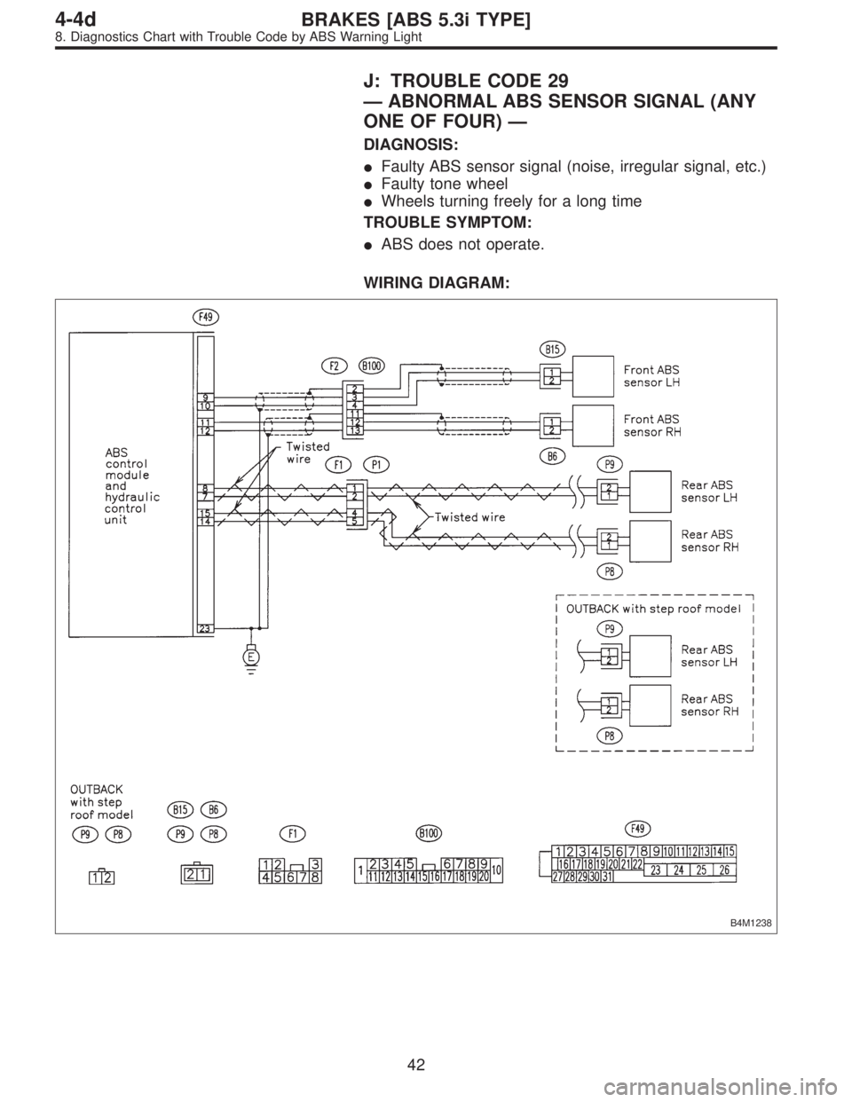
J: TROUBLE CODE 29
—ABNORMAL ABS SENSOR SIGNAL (ANY
ONE OF FOUR)—
DIAGNOSIS:
�Faulty ABS sensor signal (noise, irregular signal, etc.)
�Faulty tone wheel
�Wheels turning freely for a long time
TROUBLE SYMPTOM:
�ABS does not operate.
WIRING DIAGRAM:
B4M1238
42
4-4dBRAKES [ABS 5.3i TYPE]
8. Diagnostics Chart with Trouble Code by ABS Warning Light
Page 2919 of 3342

8J1CHECK IF THE WHEELS HAVE TURNED
FREELY FOR A LONG TIME.
: Check if the wheels have been turned freely
for more than one minute, such as when the
vehicle is jacked-up, under full-lock corner-
ing or when tire is not in contact with road
surface.
: The ABS is normal. Erase the trouble code.
NOTE:
When the wheels turn freely for a long time, such as when
the vehicle is towed or jacked-up, or when steering wheel
is continuously turned all the way, this trouble code may
sometimes occur.
: Go to step8J2.
8J2
CHECK TIRE SPECIFICATIONS.
: Are the tire specifications correct?
: Go to step8J3.
: Replace tire.
8J3
CHECK WEAR OF TIRE.
: Is the tire worn excessively?
: Replace tire.
: Go to step8J4.
8J4
CHECK TIRE PRESSURE.
: Is the tire pressure correct?
: Go to step8J5.
: Adjust tire pressure.
8J5CHECK INSTALLATION OF ABS SEN-
SOR.
Tightening torque:
32±10 N⋅m (3.3±1.0 kg-m, 24±7 ft-lb)
: Are the ABS sensor installation bolts tight-
ened securely?
: Go to step8J6.
: Tighten ABS sensor installation bolts securely.
43
4-4dBRAKES [ABS 5.3i TYPE]
8. Diagnostics Chart with Trouble Code by ABS Warning Light
Page 2920 of 3342

: Are the tone wheel installation bolts tight-
ened securely?
: Go to step8J7.
: Tighten tone wheel in")
8J6CHECK INSTALLATION OF TONE
WHEEL.
Tightening torque:
13±3 N⋅m (1.3±0.3 kg-m, 9±2.2 ft-lb)
: Are the tone wheel installation bolts tight-
ened securely?
: Go to step8J7.
: Tighten tone wheel installation bolts securely.
G4M0700
8J7
CHECK ABS SENSOR GAP.
Measure tone wheel to pole piece gap over entire perim-
eter of the wheel.
: Is the gap within the specifications shown
in the following table?
SpecificationsFront wheel Rear wheel
0.9—1.4 mm
(0.035—0.055 in)0.7—1.2 mm
(0.028—0.047 in)
G4M0701
: Go to step8J8.
: Adjust the gap.
NOTE:
Adjust the gap using spacer (Part No. 26755AA000). If
spacers cannot correct the gap, replace worn sensor or
worn tone wheel.
8J8
CHECK OSCILLOSCOPE.
: Is an oscilloscope available?
: Go to step8J9.
: Go to step8J10.
8J9
CHECK ABS SENSOR SIGNAL.
1) Raise all four wheels of ground.
2) Turn ignition switch OFF.
3) Connect the oscilloscope to the connector (F1) or con-
nector (B100).
4) Turn ignition switch ON.
44
4-4dBRAKES [ABS 5.3i TYPE]
8. Diagnostics Chart with Trouble Code by ABS Warning Light
Page 2921 of 3342
 Rotate wheels and measure voltage at specified fre-
quency.
NOTE:
When this inspection is completed, the ABS control mod-
ule sometimes stores the trouble code 29.
Connector & terminal
(B1")
B4M1242A
5) Rotate wheels and measure voltage at specified fre-
quency.
NOTE:
When this inspection is completed, the ABS control mod-
ule sometimes stores the trouble code 29.
Connector & terminal
(B100) No. 12 (+)—No. 13 (�) (Front RH):
(B100) No. 3 (+)—No.4(�) (Front LH):
(F1) No. 4 (+)—No.5(�) (Rear RH):
(F1) No. 1 (+)—No.2(�) (Rear LH):
Specified voltage: 0.12—1 V (When it is 20 Hz.)
: Is oscilloscope pattern smooth, as shown in
figure?
: Go to step8J13.
: Go to step8J10.
8J10CHECK CONTAMINATION OF ABS SEN-
SOR OR TONE WHEEL.
Remove disc rotor from hub.
: Is the ABS sensor pole piece or the tone
wheel contaminated by dirt or other foreign
matter?
: Thoroughly remove dirt or other foreign matter.
: Go to step8J11.
8J11CHECK DAMAGE OF ABS SENSOR OR
TONE WHEEL.
: Are there broken or damaged teeth in the
ABS sensor pole piece or the tone wheel?
: Replace ABS sensor or tone wheel.
: Go to step8J12.
8J12
CHECK HUB RUNOUT.
Measure hub runout.
: Is the runout less than 0.05 mm (0.0020 in)?
: Go to step8J13.
: Repair hub.
45
4-4dBRAKES [ABS 5.3i TYPE]
8. Diagnostics Chart with Trouble Code by ABS Warning Light
Page 2930 of 3342
 Turn ignition switch to OFF.
2) Disconnect connector from ABSCM&H/U.
3) Measure resistance between ABSCM&H/U and chassis
ground.
Connector & terminal")
B4M1243A
8S1CHECK GROUND CIRCUIT OF
ABSCM&H/U.
1) Turn ignition switch to OFF.
2) Disconnect connector from ABSCM&H/U.
3) Measure resistance between ABSCM&H/U and chassis
ground.
Connector & terminal
(F49) No. 23—Chassis ground:
: Is the resistance less than 0.5Ω?
: Go to step8S2.
: Repair ABSCM&H/U ground harness.
8S2CHECK POOR CONTACT IN CONNEC-
TORS.
: Is there poor contact in connectors between
battery, ignition switch and ABSCM&H/U?
: Repair connector.
: Go to step8S3.
8S3
CHECK SOURCES OF SIGNAL NOISE.
: Is the car telephone or the wireless trans-
mitter properly installed?
: Go to step8S4.
: Properly install the car telephone or the wireless
transmitter.
8S4
CHECK SOURCES OF SIGNAL NOISE.
: Are noise sources (such as an antenna)
installed near the sensor harness?
: Install the noise sources apart from the sensor
harness.
: Go to step8S5.
8S5
CHECK ABSCM&H/U.
1) Connect all connectors.
2) Erase the memory.
3) Perform inspection mode.
4) Read out the trouble code.
: Is the same trouble code as in the current
diagnosis still being output?
: Replace ABSCM&H/U.
: Go to step8S6.
54
4-4dBRAKES [ABS 5.3i TYPE]
8. Diagnostics Chart with Trouble Code by ABS Warning Light
Page 2948 of 3342
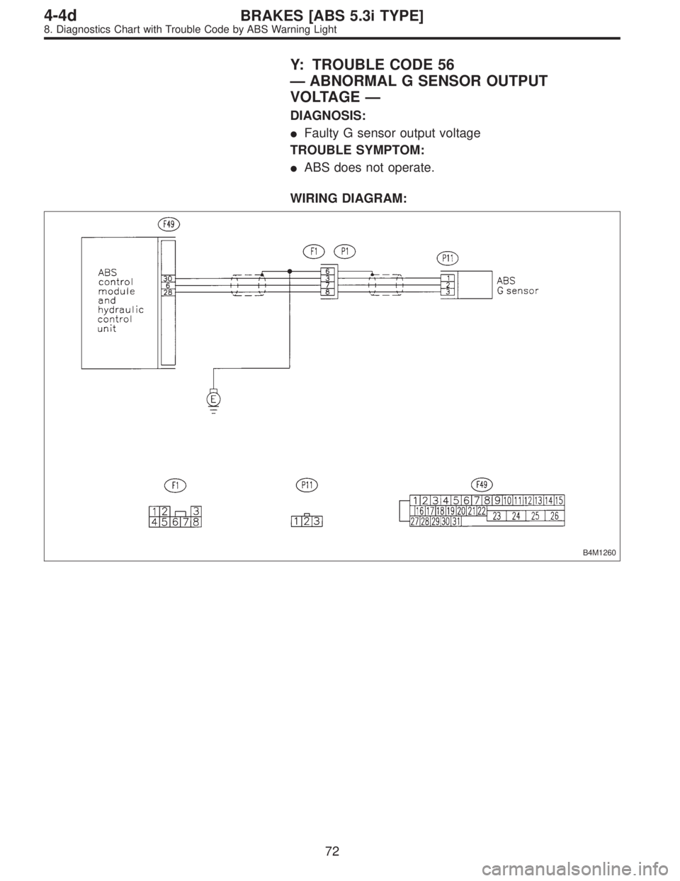
Y: TROUBLE CODE 56
—ABNORMAL G SENSOR OUTPUT
VOLTAGE—
DIAGNOSIS:
�Faulty G sensor output voltage
TROUBLE SYMPTOM:
�ABS does not operate.
WIRING DIAGRAM:
B4M1260
72
4-4dBRAKES [ABS 5.3i TYPE]
8. Diagnostics Chart with Trouble Code by ABS Warning Light
Page 2949 of 3342

8Y1CHECK ALL FOUR WHEELS FOR FREE
TURNING.
: Have the wheels been turned freely such as
when the vehicle is lifted up, or operated on
a rolling road?
: The ABS is normal. Erase the trouble code.
: Go to step8Y2.
B4M1248A
8Y2CHECK SPECIFICATIONS OF
ABSCM&H/U.
Check specifications of the mark to the ABSCM&H/U.
Mark Model
C3 AWD AT
C4 AWD MT
: Is an ABSCM for AWD model installed on a
FWD model?
CAUTION:
Be sure to turn ignition switch to OFF when removing
ABSCM&H/U.
: Replace ABSCM&H/U.
: Go to step8Y3.
B4M0911B
8Y3
CHECK INPUT VOLTAGE OF G SENSOR.
1) Turn ignition switch to OFF.
2) Remove console box.
3) Disconnect G sensor from body. (Do not disconnect
connector.)
4) Turn ignition switch to ON.
5) Measure voltage between G sensor connector termi-
nals.
Connector & terminal
(P11) No. 1 (+)—No.3(�):
: Is the voltage between 4.75 and 5.25 V?
: Go to step8Y4.
: Repair harness/connector between G sensor and
ABSCM&H/U.
73
4-4dBRAKES [ABS 5.3i TYPE]
8. Diagnostics Chart with Trouble Code by ABS Warning Light