Page 3040 of 3342
B4M0974
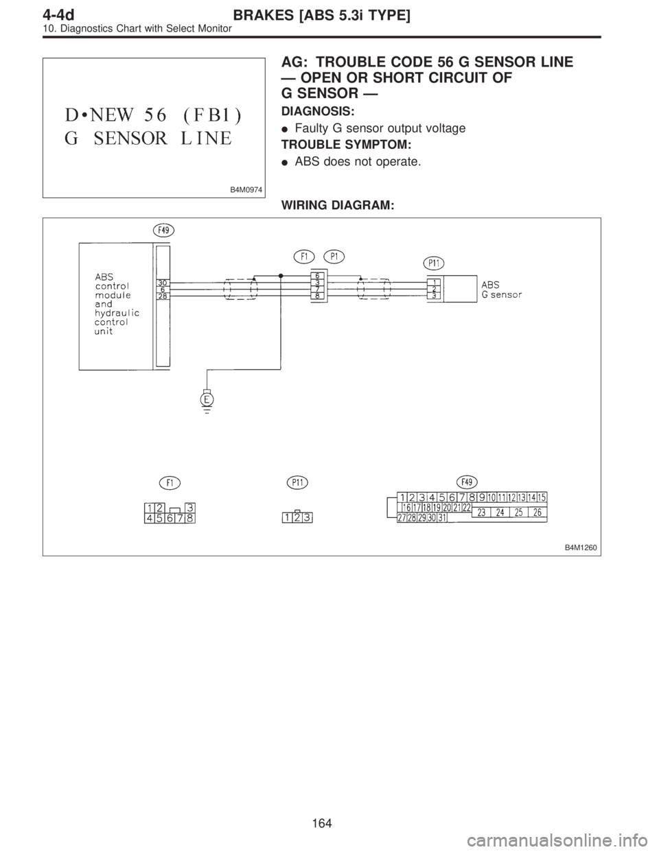
AG: TROUBLE CODE 56 G SENSOR LINE
—OPEN OR SHORT CIRCUIT OF
G SENSOR—
DIAGNOSIS:
�Faulty G sensor output voltage
TROUBLE SYMPTOM:
�ABS does not operate.
WIRING DIAGRAM:
B4M1260
164
4-4dBRAKES [ABS 5.3i TYPE]
10. Diagnostics Chart with Select Monitor
Page 3041 of 3342
![SUBARU LEGACY 1997 Service Repair Manual H4M1117
10AG1CHECK SPECIFICATIONS OF
ABSCM&H/U USING SELECT MONITOR.
1) Press [F], [0] and [0] on the select monitor.
2) Read the select monitor display.
: Is an ABSCM&H/U for 4WD model installed
on a](/manual-img/17/57434/w960_57434-3040.png "SUBARU LEGACY 1997 Service Repair Manual H4M1117
10AG1CHECK SPECIFICATIONS OF
ABSCM&H/U USING SELECT MONITOR.
1) Press [F], [0] and [0] on the select monitor.
2) Read the select monitor display.
: Is an ABSCM&H/U for 4WD model installed
on a")
H4M1117
10AG1CHECK SPECIFICATIONS OF
ABSCM&H/U USING SELECT MONITOR.
1) Press [F], [0] and [0] on the select monitor.
2) Read the select monitor display.
: Is an ABSCM&H/U for 4WD model installed
on a FWD model?
: Replace ABSCM&H/U.
: Go to step10AG2.
B4M0927
10AG2CHECK OUTPUT OF G SENSOR USING
SELECT MONITOR.
1) Press [F], [1] and [0] on the select monitor.
2) Read the select monitor display.
: Is the indicated reading between 2.1 and 2.5
V when the G sensor is in horizontal posi-
tion?
: Go to step10AG3.
: Go to step10AG6.
10AG3CHECK POOR CONTACT IN CONNEC-
TORS.
: Is there poor contact in connector between
ABSCM&H/U and G sensor?
WORD [T3C1].>
: Repair connector.
: Go to step10AG4.
10AG4
CHECK ABSCM&H/U.
1) Connect all connectors.
2) Erase the memory.
3) Perform inspection mode.
4) Read out the trouble code.
: Is the same trouble code as in the current
diagnosis still being output?
: Replace ABSCM&H/U.
: Go to step10AG5.
10AG5CHECK ANY OTHER TROUBLE CODES
APPEARANCE.
: Are other trouble codes being output?
: Proceed with the diagnosis corresponding to the
trouble code.
: A temporary poor contact.
165
4-4dBRAKES [ABS 5.3i TYPE]
10. Diagnostics Chart with Select Monitor
Page 3043 of 3342
 Turn ignition switch to OFF.
2) Disconnect connector from ABSCM&H/U.
3) Measure resistance between ABSCM&H/U conne")
B4M1261A
10AG11CHECK OPEN CIRCUIT IN G SENSOR
OUTPUT HARNESS AND GROUND HAR-
NESS.
1) Turn ignition switch to OFF.
2) Disconnect connector from ABSCM&H/U.
3) Measure resistance between ABSCM&H/U connector
terminals.
Connector & terminal
(F49) No. 30—No. 28:
: Is the resistance between 4.3 and 4.9 kΩ?
: Go to step10AG12.
: Repair harness/connector between G sensor and
ABSCM&H/U.
10AG12CHECK POOR CONTACT IN CONNEC-
TORS.
: Is there poor contact in connector between
ABSCM&H/U and G sensor?
WORD [T3C1].>
: Repair connector.
: Go to step10AG13.
10AG13
CHECK ABSCM&H/U.
1) Connect all connectors.
2) Erase the memory.
3) Perform inspection mode.
4) Read out the trouble code.
: Is the same trouble code as in the current
diagnosis still being output?
: Replace ABSCM&H/U.
: Go to step10AG14.
10AG14CHECK ANY OTHER TROUBLE CODES
APPEARANCE.
: Are other trouble codes being output?
: Proceed with the diagnosis corresponding to the
trouble code.
: A temporary poor contact.
167
4-4dBRAKES [ABS 5.3i TYPE]
10. Diagnostics Chart with Select Monitor
Page 3044 of 3342
B4M0911B
10AG15
CHECK INPUT VOLTAGE OF G SENSOR.
1) Turn ignition switch to OFF.
2) Remove console box.
3) Disconnect G sensor from body. (Do not disconnect
connector.)
4) Turn ignition switch to ON.
5) Measure voltage between G sensor connector termi-
nals.
Connector & terminal
(P11) No. 1 (+)—No.3(�):
: Is the voltage between 4.75 and 5.25 V?
: Go to step10AG16.
: Repair harness/connector between G sensor and
ABSCM&H/U.
B4M1261A
10AG16CHECK OPEN CIRCUIT IN G SENSOR
OUTPUT HARNESS AND GROUND HAR-
NESS.
1) Turn ignition switch to OFF.
2) Disconnect connector from ABSCM&H/U.
3) Measure resistance between ABSCM&H/U connector
terminals.
Connector & terminal
(F49) No. 30—No. 28:
: Is the resistance between 4.3 and 4.9 kΩ?
: Go to step10AG17.
: Repair harness/connector between G sensor and
ABSCM&H/U.
168
4-4dBRAKES [ABS 5.3i TYPE]
10. Diagnostics Chart with Select Monitor
Page 3045 of 3342
 Disconnect connector from G sensor.
2) Measure resistance between ABSCM&H/U connector
and chassis ground.
Connector & terminal
(F49) No")
B4M1262A
10AG17CHECK GROUND SHORT IN G SENSOR
OUTPUT HARNESS.
1) Disconnect connector from G sensor.
2) Measure resistance between ABSCM&H/U connector
and chassis ground.
Connector & terminal
(F49) No. 6—Chassis ground:
: Is the resistance more than 1 MΩ?
: Go to step10AG18.
: Repair harness between G sensor and
ABSCM&H/U.
B4M0915
10AG18
CHECK G SENSOR.
1) Connect connector to G sensor.
2) Connect connector to ABSCM&H/U.
3) Turn ignition switch to ON.
4) Measure voltage between G sensor connector termi-
nals.
Connector & terminal
(P11) No. 2 (+)—No.1(�):
: Is the voltage between 2.1 and 2.5 V when G
sensor is horizontal?
: Go to step10AG19.
: Replace G sensor.
B4M0917A
10AG19
CHECK G SENSOR.
Measure voltage between G sensor connector terminals.
Connector & terminal
(P11) No. 2 (+)—No.1(�):
: Is the voltage between 3.7 and 4.1 V when G
sensor is inclined forwards to 90°?
: Go to step10AG20.
: Replace G sensor.
169
4-4dBRAKES [ABS 5.3i TYPE]
10. Diagnostics Chart with Select Monitor
Page 3046 of 3342
B4M0918A
10AG20
CHECK G SENSOR.
Measure voltage between G sensor connector terminals.
Connector & terminal
(P11) No. 2 (+)—No.1(�):
: Is the voltage between 0.5 and 0.9 V when G
sensor is inclined backwards to 90°?
: Go to step10AG21.
: Replace G sensor.
10AG21CHECK POOR CONTACT IN CONNEC-
TORS.
Turn ignition switch to OFF.
: Is there poor contact in connector between
ABSCM&H/U and G sensor?
WORD [T3C1].>
: Repair connector.
: Go to step10AG22.
10AG22
CHECK ABSCM&H/U.
1) Connect all connectors.
2) Erase the memory.
3) Perform inspection mode.
4) Read out the trouble code.
: Is the same trouble code as in the current
diagnosis still being output?
: Replace ABSCM&H/U.
: Go to step10AG23.
10AG23CHECK ANY OTHER TROUBLE CODES
APPEARANCE.
: Are other trouble codes being output?
: Proceed with the diagnosis corresponding to the
trouble code.
: A temporary poor contact.
170
4-4dBRAKES [ABS 5.3i TYPE]
10. Diagnostics Chart with Select Monitor
Page 3047 of 3342
B4M0982
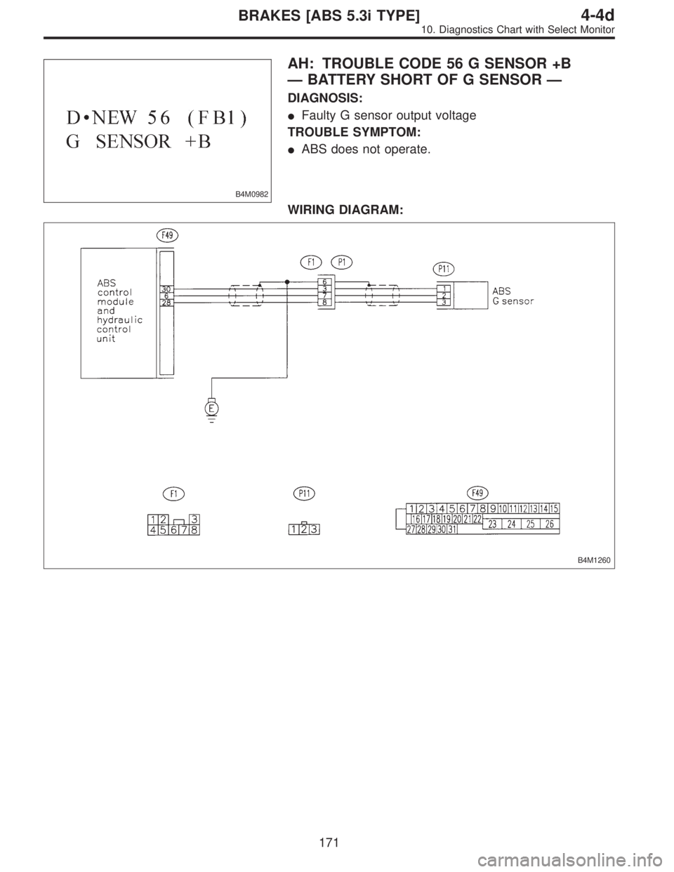
AH: TROUBLE CODE 56 G SENSOR +B
—BATTERY SHORT OF G SENSOR—
DIAGNOSIS:
�Faulty G sensor output voltage
TROUBLE SYMPTOM:
�ABS does not operate.
WIRING DIAGRAM:
B4M1260
171
4-4dBRAKES [ABS 5.3i TYPE]
10. Diagnostics Chart with Select Monitor
Page 3048 of 3342
![SUBARU LEGACY 1997 Service Repair Manual B4M0927
10AH1CHECK OUTPUT OF G SENSOR USING
SELECT MONITOR.
1) Press [F], [1] and [0] on the select monitor.
2) Read the select monitor display.
: Is the indicated reading between 2.1 and 2.5
V when t](/manual-img/17/57434/w960_57434-3047.png "SUBARU LEGACY 1997 Service Repair Manual B4M0927
10AH1CHECK OUTPUT OF G SENSOR USING
SELECT MONITOR.
1) Press [F], [1] and [0] on the select monitor.
2) Read the select monitor display.
: Is the indicated reading between 2.1 and 2.5
V when t")
B4M0927
10AH1CHECK OUTPUT OF G SENSOR USING
SELECT MONITOR.
1) Press [F], [1] and [0] on the select monitor.
2) Read the select monitor display.
: Is the indicated reading between 2.1 and 2.5
V when the G sensor is in horizontal posi-
tion?
: Replace ABSCM&H/U.
: Go to step10AH2.
B4M1263A
10AH2
CHECK BATTERY SHORT OF HARNESS.
1) Turn ignition switch to OFF.
2) Remove console box.
3) Disconnect connector from G sensor.
4) Disconnect connector from ABSCM&H/U.
5) Measure voltage between ABSCM&H/U connector and
chassis ground.
Connector & terminal
(F49) No. 6 (+)—Chassis ground (�):
: Is the voltage less than 1 V?
: Go to step10AH3.
: Repair harness between G sensor and
ABSCM&H/U.
B4M1263A
10AH3
CHECK BATTERY SHORT OF HARNESS.
1) Turn ignition switch to ON.
2) Measure voltage between ABSCM&H/U connector and
chassis ground.
Connector & terminal
(F49) No. 6 (+)—Chassis ground (�):
: Is the voltage less than 1 V?
: Go to step10AH4.
: Repair harness between G sensor and
ABSCM&H/U.
172
4-4dBRAKES [ABS 5.3i TYPE]
10. Diagnostics Chart with Select Monitor
 Turn ignition switch to OFF.
2) Remove console box.
3) Disconnect G sensor from body. (Do not disconnect
connector.)
4) Turn ignition switch to ON.")
 No. 2 (+)—No.1(�):
: Is the voltage between 0.5 and 0.9 V when G
sensor is inclined b")