Page 3050 of 3342
B4M0984
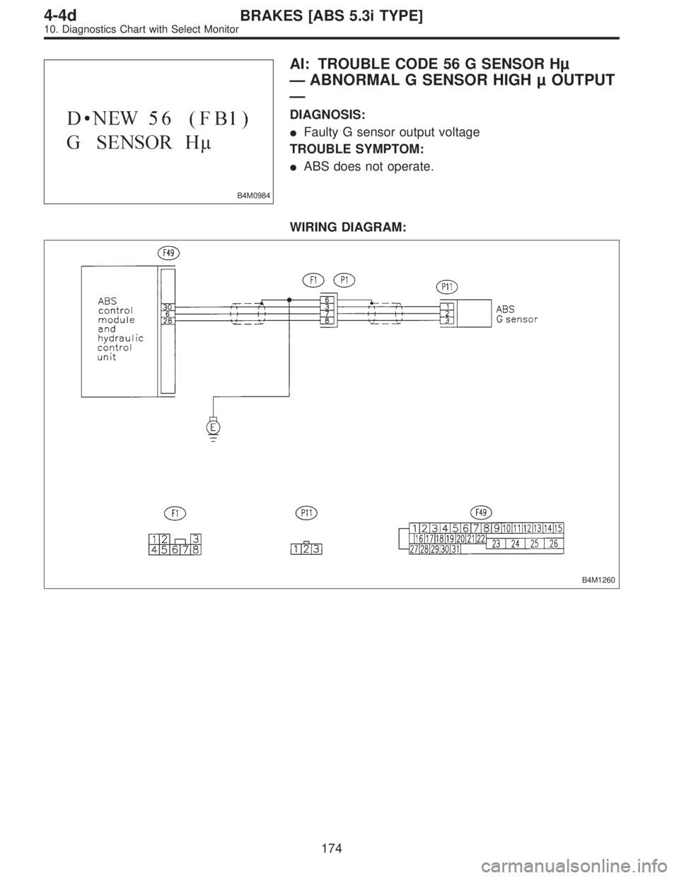
AI: TROUBLE CODE 56 G SENSOR Hµ
—ABNORMAL G SENSOR HIGH µ OUTPUT
—
DIAGNOSIS:
�Faulty G sensor output voltage
TROUBLE SYMPTOM:
�ABS does not operate.
WIRING DIAGRAM:
B4M1260
174
4-4dBRAKES [ABS 5.3i TYPE]
10. Diagnostics Chart with Select Monitor
Page 3051 of 3342
B4M0927
10AI1CHECK OUTPUT OF G SENSOR USING
SELECT MONITOR.
1) Press [F], [1] and [0] on the select monitor.
2) Read the select monitor display.
: Is the indicated reading 2.3±0.2 V when the
G sensor is in horizontal position?
: Go to step10AI2.
: Go to step10AI6.
10AI2CHECK POOR CONTACT IN CONNEC-
TORS.
Turn ignition switch to OFF.
: Is there poor contact in connector between
ABSCM&H/U and G sensor?
WORD [T3C1].>
: Repair connector.
: Go to step10AI3.
10AI3
CHECK ABSCM&H/U.
1) Connect all connectors.
2) Erase the memory.
3) Perform inspection mode.
4) Read out the trouble code.
: Is the same trouble code as in the current
diagnosis still being output?
: Replace ABSCM&H/U.
: Go to step10AI4.
10AI4CHECK ANY OTHER TROUBLE CODES
APPEARANCE.
: Are other trouble codes being output?
: Proceed with the diagnosis corresponding to the
trouble code.
: A temporary poor contact.
175
4-4dBRAKES [ABS 5.3i TYPE]
10. Diagnostics Chart with Select Monitor
Page 3052 of 3342
B4M1261A
10AI5CHECK OPEN CIRCUIT IN G SENSOR
OUTPUT HARNESS AND GROUND HAR-
NESS.
1) Turn ignition switch to OFF.
2) Disconnect connector from ABSCM&H/U.
3) Measure resistance between ABSCM&H/U connector
terminals.
Connector & terminal
(F49) No. 30—No. 28:
: Is the resistance between 4.3 and 4.9 kΩ?
: Go to step10AI6.
: Repair harness/connector between G sensor and
ABSCM&H/U.
B4M1264A
10AI6
CHECK GROUND SHORT OF HARNESS.
Measure resistance between ABSCM&H/U connector and
chassis ground.
Connector & terminal
(F49) No. 28—Chassis ground:
: Is the resistance more than 1 MΩ?
: Go to step10AI7.
: Repair harness between G sensor and
ABSCM&H/U.
Replace ABSCM&H/U.
176
4-4dBRAKES [ABS 5.3i TYPE]
10. Diagnostics Chart with Select Monitor
Page 3053 of 3342
B4M0915
10AI7
CHECK G SENSOR.
1) Remove console box.
2) Remove G sensor from vehicle.
3) Connect connector to G sensor.
4) Connect connector to ABSCM&H/U.
5) Turn ignition switch to ON.
6) Measure voltage between G sensor connector termi-
nals.
Connector & terminal
(P11) No. 2 (+)—No.1(�):
: Is the voltage between 2.1 and 2.5 V when G
sensor is horizontal?
: Go to step10AI8.
: Replace G sensor.
B4M0917A
10AI8
CHECK G SENSOR.
Measure voltage between G sensor connector terminals.
Connector & terminal
(R70) No. 2 (+)—No.1(�):
: Is the voltage between 3.7 and 4.1 V when G
sensor is inclined forwards to 90°?
: Go to step10AI9.
: Replace G sensor.
B4M0918A
10AI9
CHECK G SENSOR.
Measure voltage between G sensor connector terminals.
Connector & terminal
(R70) No. 2 (+)—No.1(�):
: Is the voltage between 0.5 and 0.9 V when G
sensor is inclined backwards to 90°?
: Go to step10AI10.
: Replace G sensor.
177
4-4dBRAKES [ABS 5.3i TYPE]
10. Diagnostics Chart with Select Monitor
Page 3055 of 3342
B4M0813
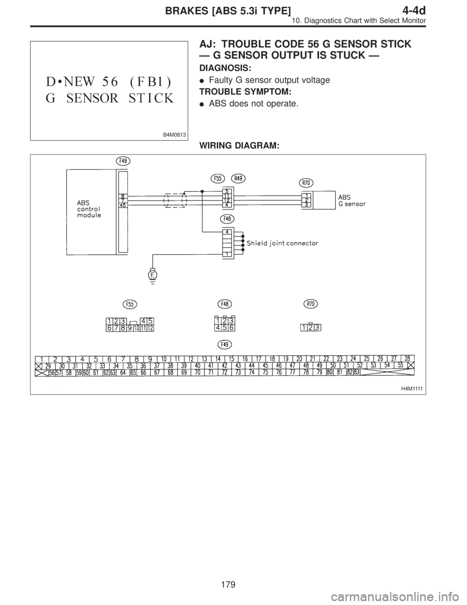
AJ: TROUBLE CODE 56 G SENSOR STICK
—G SENSOR OUTPUT IS STUCK—
DIAGNOSIS:
�Faulty G sensor output voltage
TROUBLE SYMPTOM:
�ABS does not operate.
WIRING DIAGRAM:
H 4 M 1111
179
4-4dBRAKES [ABS 5.3i TYPE]
10. Diagnostics Chart with Select Monitor
Page 3056 of 3342

10AJ1CHECK ALL FOUR WHEELS FOR FREE
TURNING.
: Have the wheels been turned freely such as
when the vehicle is lifted up, or operated on
a rolling road?
: The ABS is normal. Erase the trouble code.
: Go to step10AJ2.
B4M0927
10AJ2CHECK OUTPUT OF G SENSOR USING
SELECT MONITOR.
1) Press [F], [1] and [0] on the select monitor.
2) Read the select monitor display.
: Is the indicated reading between 2.1 and 2.5
V when the vehicle is in horizontal position?
: Go to step10AJ3.
: Go to step10AJ8.
B4M0917A
10AJ3CHECK OUTPUT OF G SENSOR USING
SELECT MONITOR.
1) Turn ignition switch to OFF.
2) Remove console box.
3) Remove G sensor from vehicle. (Do not disconnect
connector.)
4) Turn ignition switch to ON.
5) Press [F], [1] and [0] on the select monitor.
6) Read the select monitor display.
: Is the indicated reading between 3.7 and 4.1
V when G sensor is inclined forwards to
90°?
: Go to step10AJ4.
: Replace G sensor.
B4M0918A
10AJ4CHECK OUTPUT OF G SENSOR USING
SELECT MONITOR.
Read the select monitor display.
: Is the indicated reading between 0.5 and 0.9
V when G sensor is inclined backwards to
90°?
: Go to step10AJ5.
: Replace G sensor.
180
4-4dBRAKES [ABS 5.3i TYPE]
10. Diagnostics Chart with Select Monitor
Page 3057 of 3342
![SUBARU LEGACY 1997 Service Repair Manual 10AJ5CHECK POOR CONTACT IN CONNEC-
TORS.
Turn ignition switch to OFF.
: Is there poor contact in connector between
ABSCM&H/U and G sensor? <Ref. to FORE-
WORD [T3C1].>
: Repair connector.
: Go to step](/manual-img/17/57434/w960_57434-3056.png "SUBARU LEGACY 1997 Service Repair Manual 10AJ5CHECK POOR CONTACT IN CONNEC-
TORS.
Turn ignition switch to OFF.
: Is there poor contact in connector between
ABSCM&H/U and G sensor? <Ref. to FORE-
WORD [T3C1].>
: Repair connector.
: Go to step")
10AJ5CHECK POOR CONTACT IN CONNEC-
TORS.
Turn ignition switch to OFF.
: Is there poor contact in connector between
ABSCM&H/U and G sensor?
WORD [T3C1].>
: Repair connector.
: Go to step10AJ6.
10AJ6
CHECK ABSCM&H/U.
1) Connect all connectors.
2) Erase the memory.
3) Perform inspection mode.
4) Read out the trouble code.
: Is the same trouble code as in the current
diagnosis still being output?
: Replace ABSCM&H/U.
: Go to step10AJ7.
10AJ7CHECK ANY OTHER TROUBLE CODES
APPEARANCE.
: Are other trouble codes being output?
: Proceed with the diagnosis corresponding to the
trouble code.
: A temporary poor contact.
B4M1261A
10AJ8CHECK OPEN CIRCUIT IN G SENSOR
OUTPUT HARNESS AND GROUND HAR-
NESS.
1) Turn ignition switch to OFF.
2) Disconnect connector from ABSCM&H/U.
3) Measure resistance between ABSCM&H/U connector
terminals.
Connector & terminal
(F49) No. 30—No. 28:
: Is the resistance between 4.3 and 4.9 kΩ?
: Go to step10AJ9.
: Repair harness/connector between G sensor and
ABSCM&H/U.
181
4-4dBRAKES [ABS 5.3i TYPE]
10. Diagnostics Chart with Select Monitor
Page 3058 of 3342
B4M0915
10AJ9
CHECK G SENSOR.
1) Remove console box.
2) Remove G sensor from vehicle.
3) Connect connector to G sensor.
4) Connect connector to ABSCM&H/U.
5) Turn ignition switch to ON.
6) Measure voltage between G sensor connector termi-
nals.
Connector & terminal
(P11) No. 2 (+)—No.1(�):
: Is the voltage between 2.1 and 2.5 V when G
sensor is horizontal?
: Go to step10AJ10.
: Replace G sensor.
B4M0917A
10AJ10
CHECK G SENSOR.
Measure voltage between G sensor connector terminals.
Connector & terminal
(P11) No. 2 (+)—No.1(�):
: Is the voltage between 3.7 and 4.1 V when G
sensor is inclined forwards to 90°?
: Go to step10AJ11.
: Replace G sensor.
B4M0918A
10AJ11
CHECK G SENSOR.
Measure voltage between G sensor connector terminals.
Connector & terminal
(P11) No. 2 (+)—No.1(�):
: Is the voltage between 0.5 and 0.9 V when G
sensor is inclined backwards to 90°?
: Go to step10AJ12.
: Replace G sensor.
182
4-4dBRAKES [ABS 5.3i TYPE]
10. Diagnostics Chart with Select Monitor
![SUBARU LEGACY 1997 Service Repair Manual B4M0927
10AI1CHECK OUTPUT OF G SENSOR USING
SELECT MONITOR.
1) Press [F], [1] and [0] on the select monitor.
2) Read the select monitor display.
: Is the indicated reading 2.3±0.2 V when the
G sensor](/manual-img/17/57434/w960_57434-3050.png "SUBARU LEGACY 1997 Service Repair Manual B4M0927
10AI1CHECK OUTPUT OF G SENSOR USING
SELECT MONITOR.
1) Press [F], [1] and [0] on the select monitor.
2) Read the select monitor display.
: Is the indicated reading 2.3±0.2 V when the
G sensor")
 Turn ignition switch to OFF.
2) Disconnect connector from ABSCM&H/U.
3) Measure resistance between ABSCM&H/U connec")
 Remove console box.
2) Remove G sensor from vehicle.
3) Connect connector to G sensor.
4) Connect connector to ABSCM&H/U.
5) Turn ignition switch to ON.
6) Measure vol")
 Remove console box.
2) Remove G sensor from vehicle.
3) Connect connector to G sensor.
4) Connect connector to ABSCM&H/U.
5) Turn ignition switch to ON.
6) Measure vol")