Page 2710 of 3342
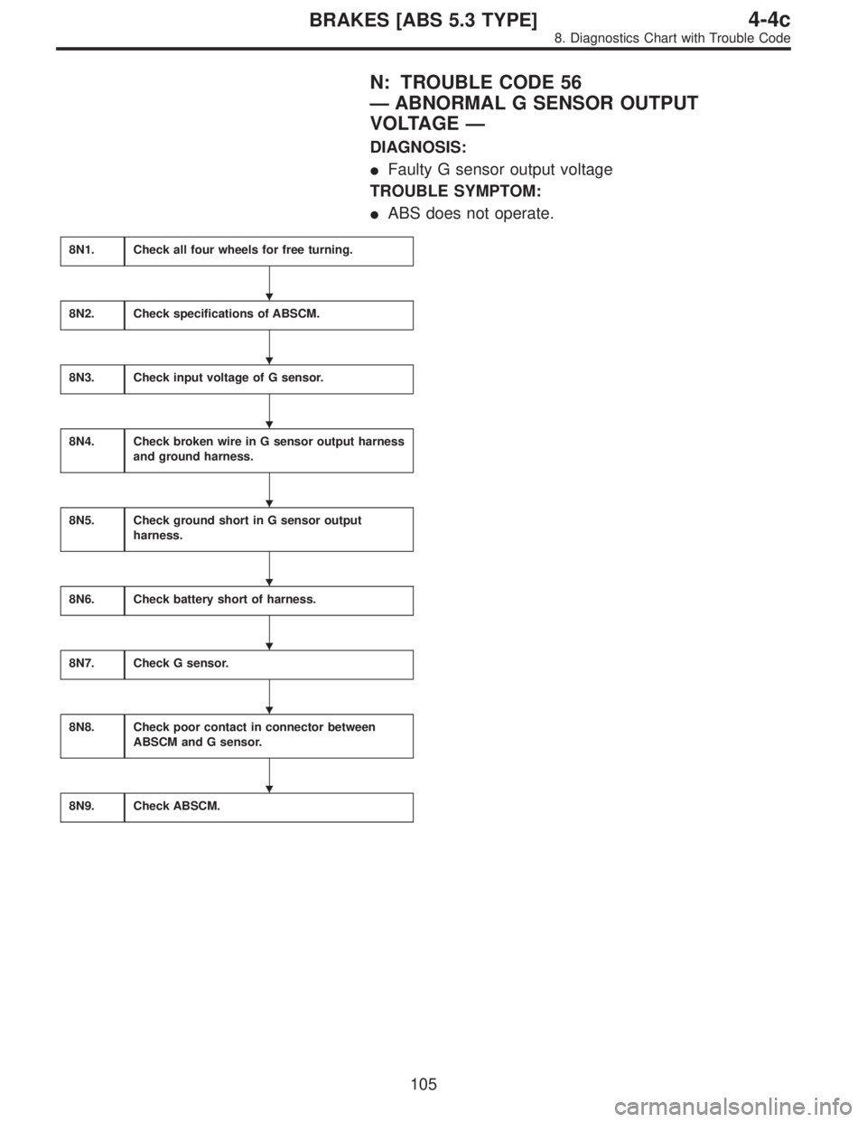
N: TROUBLE CODE 56
—ABNORMAL G SENSOR OUTPUT
VOLTAGE—
DIAGNOSIS:
�Faulty G sensor output voltage
TROUBLE SYMPTOM:
�ABS does not operate.
8N1.Check all four wheels for free turning.
8N2.Check specifications of ABSCM.
8N3.Check input voltage of G sensor.
8N4.Check broken wire in G sensor output harness
and ground harness.
8N5.Check ground short in G sensor output
harness.
8N6.Check battery short of harness.
8N7.Check G sensor.
8N8.Check poor contact in connector between
ABSCM and G sensor.
8N9.Check ABSCM.
�
�
�
�
�
�
�
�
105
4-4cBRAKES [ABS 5.3 TYPE]
8. Diagnostics Chart with Trouble Code
Page 2712 of 3342
B4M0911B
8N3
CHECK INPUT VOLTAGE OF G SENSOR.
1) Turn ignition switch to OFF.
2) Remove console box.
3) Disconnect G sensor from body. (Do not disconnect
connector.)
4) Turn ignition switch to ON.
5) Measure voltage between G sensor connector termi-
nals.
: Connector & terminal
(P11) No. 1 (+)—No.3(�)
Is voltage 5±0.25 V?
: Go to step8N4.
: Repair harness connector between G sensor and
ABSCM.
B4M0912A
8N4CHECK BROKEN WIRE IN G SENSOR
OUTPUT HARNESS AND GROUND HAR-
NESS.
1) Turn ignition switch to OFF.
2) Disconnect connector from ABSCM.
3) Measure resistance between ABSCM connector termi-
nals.
: Connector & terminal
(F49) No. 7—No. 45
Is resistance 4.6±0.3 kΩ?
: Go to step8N5.
: Repair harness between G sensor and ABSCM.
107
4-4cBRAKES [ABS 5.3 TYPE]
8. Diagnostics Chart with Trouble Code
Page 2713 of 3342
B4M0913A
8N5CHECK GROUND SHORT IN G SENSOR
OUTPUT HARNESS.
1) Disconnect connector from G sensor.
2) Measure resistance between ABSCM connector and
chassis ground.
: Connector & terminal
(F49) No. 7—Chassis ground
Is resistance more than 1 MΩ?
: Go to step8N6.
: Repair harness between G sensor and ABSCM.
B4M0914A
8N6
CHECK BATTERY SHORT OF HARNESS.
1) Turn ignition switch to ON.
2) Measure voltage between ABSCM connector and chas-
sis ground.
: Connector & terminal
(F49) No. 7 (+)—Chassis ground (�)
Is voltage 0 V?
: Go to next step.
: Repair harness between G sensor and ABSCM.
3) Turn ignition switch to OFF.
4) Measure voltage between ABSCM connector and chas-
sis ground.
: Connector & terminal
(F49) No. 7 (+)—Chassis ground (�)
Is voltage 0 V?
: Go to step8N7.
: Repair harness between G sensor and ABSCM.
108
4-4cBRAKES [ABS 5.3 TYPE]
8. Diagnostics Chart with Trouble Code
Page 2714 of 3342
B4M0915
8N7
CHECK G SENSOR.
1) Remove G sensor from vehicle.
2) Connect connector to G sensor.
3) Connect connector to ABSCM.
4) Turn ignition switch to ON.
5) Measure voltage between G sensor connector termi-
nals.
: Connector & terminal
(P11) No. 2 (+)—No.1(�)
Is voltage 2.3±0.2 V when G sensor is hori-
zontal?
: Go to next.
: Replace G sensor.
B4M0917A
: Connector & terminal
(P11) No. 2 (+)—No.1(�)
Is voltage 3.9±0.2 V when G sensor is
inclined forwards to 90°?
: Go to next.
: Replace G sensor.
B4M0918A
: Connector & terminal
(P11) No. 2 (+)—No.1(�)
Is voltage 0.7±0.2 V when G sensor is
inclined backwards to 90°?
: Go to step8N8.
: Replace G sensor.
8N8CHECK POOR CONTACT IN CONNEC-
TOR BETWEEN ABSCM AND G SENSOR.
: Is there poor contact in connector between
ABSCM and G sensor?
: Repair connector.
: Go to step8N9.
109
4-4cBRAKES [ABS 5.3 TYPE]
8. Diagnostics Chart with Trouble Code
Page 2716 of 3342

Function code
Measuring items Cont")
G2M0096
9. Select Monitor Function Mode
Applicable cartridge of select monitor: No. 498345700
A: LIST OF FUNCTION MODE
1. F MODE (ROM ID, ANALOG DATA ARE
DISPLAYED.)
Function code
Measuring items Contents to be monitored Scroll Ref. to
Code Abbreviation
F00 ROM ID ECM identificationROM ID number of ECM is read and enabled commu-
nication state is displayed.Possible 4-4c [T9B0]
F01 FRFR wheel speed
(mile/h)Wheel speed detected by the FR ABS sensor is dis-
played in mile/h.Possible 4-4c [T9C0]
F02 FLFL wheel speed
(mile/h)Wheel speed detected by the FL ABS sensor is dis-
played in mile/h.Possible 4-4c [T9D0]
F03 RRRR wheel speed
(mile/h)Wheel speed detected by the RR ABS sensor is dis-
played in mile/h.Possible 4-4c [T9E0]
F04 RLRL wheel speed
(mile/h)Wheel speed detected by the RL ABS sensor is dis-
played in mile/h.Possible 4-4c [T9F0]
F05 FRFR wheel speed
(km/h)Wheel speed detected by the FR ABS sensor is dis-
played in km/h.Possible 4-4c [T9C0]
F06 FLFL wheel speed
(km/h)Wheel speed detected by the FL ABS sensor is dis-
played in km/h.Possible 4-4c [T9D0]
F07 RRRR wheel speed
(km/h)Wheel speed detected by the RR ABS sensor is dis-
played in km/h.Possible 4-4c [T9E0]
F08 RLRL wheel speed
(km/h)Wheel speed detected by the RL ABS sensor is dis-
played in km/h.Possible 4-4c [T9F0]
F09 BLSStop light switch
monitorStop light switch monitor voltage is displayed. Possible 4-4c [T9G0]
F10 G-SENSG sensor output volt-
age (V)Refers to vehicle acceleration detecting by the analog
G sensor. It appears on the select monitor display in
volts.Possible4-4c [T9H0]
111
4-4cBRAKES [ABS 5.3 TYPE]
9. Select Monitor Function Mode
Page 2718 of 3342

Function code
Measuring items Contents to be monitored Scroll Ref. to
Code Abbreviation
FC0 D⋅CLRHistory of trouble
codes is erased.Funct")
4. FC MODE (TROUBLE CODES AND FREEZE
FRAME DATA ARE ERASED.)
Function code
Measuring items Contents to be monitored Scroll Ref. to
Code Abbreviation
FC0 D⋅CLRHistory of trouble
codes is erased.Function of clearing trouble code. Possible 4-4c [T9J0]
5. FD MODE (ABS SEQUENCE CHECK MODE)
Function code
Measuring items Contents to be monitored Scroll Ref. to
Code Abbreviation
FD1 A⋅CHKABS sequence con-
trolPerform ABS sequence control by operating valve and
pump motor sequentially.Impossible4-4
[W20D0]
6. FE MODE (FREEZE FRAME DATA)
NOTE:
Data stored at the time of trouble occurrence is shown on
display.
Function code
Measuring items Contents to be monitored Scroll Ref. to
Code Abbreviation
FE1 FR FR wheel speed (mile/h)Wheel speed detected by the FR ABS sensor is displayed in
mile/h.Possible 4-4c [T9K0]
FE2 FL FL wheel speed (mile/h)Wheel speed detected by the FL ABS sensor is displayed in
mile/h.Possible 4-4c [T9L0]
FE3 RR RR wheel speed (mile/h)Wheel speed detected by the RR ABS sensor is displayed in
mile/h.Possible 4-4c [T9M0]
FE4 RL RL wheel speed (mile/h)Wheel speed detected by the RL ABS sensor is displayed in
mile/h.Possible 4-4c [T9N0]
FE5 FR FR wheel speed (km/h)Wheel speed detected by the FR ABS sensor is displayed in
km/h.Possible 4-4c [T9K0]
FE6 FL FL wheel speed (km/h)Wheel speed detected by the FL ABS sensor is displayed in
km/h.Possible 4-4c [T9L0]
FE7 RR RR wheel speed (km/h)Wheel speed detected by the RR ABS sensor is displayed in
km/h.Possible 4-4c [T9M0]
FE8 RL RL wheel speed (km/h)Wheel speed detected by the RL ABS sensor is displayed in
km/h.Possible 4-4c [T9N0]
FE13 POWERABSCM power supply
voltage (V)Power (in volts) supplied to ABSCM appears on the select
monitor display.Possible 4-4c [T9O0]
FE14 G-SENSG sensor output voltage
(V)Refers to vehicle acceleration detected by the analog G sen-
sor. It appears on the select monitor display in volts.Possible 4-4c [T9P0]
FE15MM Motor relay monitor LED 1 comes on when motor relay is on.
Possible 4-4c [T9Q0] B1 Stop light switchLED 2 comes on with the stop light switch on (with the brake
pedal depressed).
AT AT ABS signal LED 3 comes on when ABS control is on.
CM CCM signal LED 4 comes on when ABS control is on.
A0 ABS control LED 5 comes on when ABS control is on.
11 3
4-4cBRAKES [ABS 5.3 TYPE]
9. Select Monitor Function Mode
Page 2722 of 3342
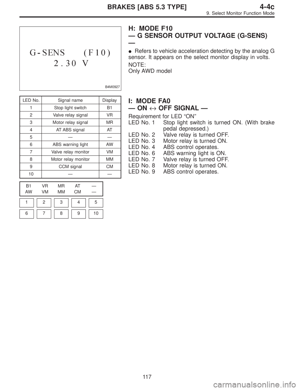
B4M0927
H: MODE F10
—G SENSOR OUTPUT VOLTAGE (G-SENS)
—
�Refers to vehicle acceleration detecting by the analog G
sensor. It appears on the select monitor display in volts.
NOTE:
Only AWD model
LED No. Signal name Display
1 Stop light switch B1
2 Valve relay signal VR
3 Motor relay signal MR
4 AT ABS signal AT
5——
6 ABS warning light AW
7 Valve relay monitor VM
8 Motor relay monitor MM
9 CCM signal CM
10——
B1 VR MR AT—
AW VM MM CM—
1
2345
678910
I: MODE FA0
—ON↔OFF SIGNAL—
Requirement for LED“ON”
LED No. 1 Stop light switch is turned ON. (With brake
pedal depressed.)
LED No. 2 Valve relay is turned OFF.
LED No. 3 Motor relay is turned ON.
LED No. 4 ABS control operates.
LED No. 6 ABS warning light is ON.
LED No. 7 Valve relay is turned OFF.
LED No. 8 Motor relay is turned ON.
LED No. 9 ABS control operates.
11 7
4-4cBRAKES [ABS 5.3 TYPE]
9. Select Monitor Function Mode
Page 2726 of 3342
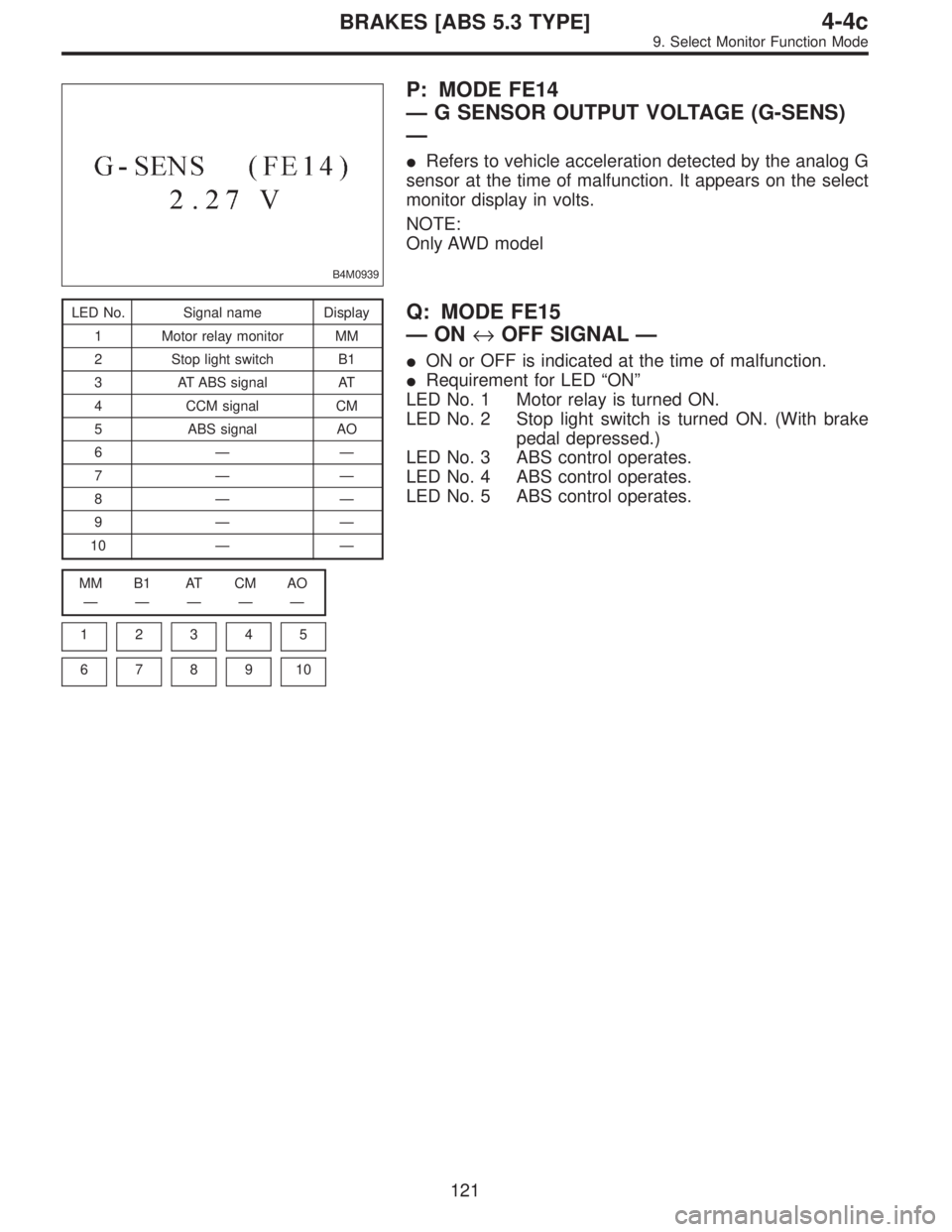
B4M0939
P: MODE FE14
—G SENSOR OUTPUT VOLTAGE (G-SENS)
—
�Refers to vehicle acceleration detected by the analog G
sensor at the time of malfunction. It appears on the select
monitor display in volts.
NOTE:
Only AWD model
LED No. Signal name Display
1 Motor relay monitor MM
2 Stop light switch B1
3 AT ABS signal AT
4 CCM signal CM
5 ABS signal AO
6——
7——
8——
9——
10——
MM B1 AT CM AO
—————
1
2345
678910
Q: MODE FE15
—ON↔OFF SIGNAL—
�ON or OFF is indicated at the time of malfunction.
�Requirement for LED“ON”
LED No. 1 Motor relay is turned ON.
LED No. 2 Stop light switch is turned ON. (With brake
pedal depressed.)
LED No. 3 ABS control operates.
LED No. 4 ABS control operates.
LED No. 5 ABS control operates.
121
4-4cBRAKES [ABS 5.3 TYPE]
9. Select Monitor Function Mode
 Turn ignition switch to OFF.
2) Remove console box.
3) Disconnect G sensor from body. (Do not disconnect
connector.)
4) Turn ignition switch to ON.
5)")
 Disconnect connector from G sensor.
2) Measure resistance between ABSCM connector and
chassis ground.
: Connector & terminal
(F49) No. 7�")
 Remove G sensor from vehicle.
2) Connect connector to G sensor.
3) Connect connector to ABSCM.
4) Turn ignition switch to ON.
5) Measure voltage between G sensor connect")