Page 1039 of 3342
 After completion of fitting, make sure that the selector
lever operates smoothly all across the operating range.
11) Connect the harnesses and check the following items.
(1) The engine starts oper")
10) After completion of fitting, make sure that the selector
lever operates smoothly all across the operating range.
11) Connect the harnesses and check the following items.
(1) The engine starts operating when selector lever is
in position“P”, but not in other positions.
(2) The back-up light is lit when the selector lever is in
position“R”, but not in other positions.
B3M0348A
12) Check selector lever operation.
WARNING:
Stop the engine while checking operation of selector
lever.
(1) Check that selector lever does not move from“N”
to“R”without pushing the button.
(2) Check that selector lever does not move from“R”
to“P”without pushing the button.
(3) Check that selector lever does not move from“P”
to“R”without pushing the button and the brake pedal
depressed. [With ignition key set at“ON”.]
(4) Check that selector lever does not move from“3”to
“2”without pushing the button.
13) Check shift-lock system.
(1) Ensure ignition switch rotates from“ACC”to
“LOCK”when the selector lever is set at“P”. Also check
that ignition key can be removed from the“LOCK”posi-
tion only.
(2) Ensure selector lever moves from“P”to any other
position when the brake pedal is depressed with igni-
tion key set at“ON”or“START”.
16
3-3SERVICE PROCEDURE
2. Automatic Transmission
Page 1197 of 3342
 Insert combination switch to upper column shaft, and
install lower column cover with tilt lever held in the lowered
position. Then route ignition key harness and combination
swi")
B4M0555
D: ASSEMBLY
1) Insert combination switch to upper column shaft, and
install lower column cover with tilt lever held in the lowered
position. Then route ignition key harness and combination
switch harness between column cover mounting bosses.
2) Fit upper column cover to lower column cover, and
tighten combination switch and column cover.
Tightening torque:
1.2±0.2 N⋅m (0.12±0.02 kg-m, 0.9±0.1 ft-lb)
CAUTION:
Don’t overtorque screw.
E: INSTALLATION
1) Insert end of steering shaft into toe board grommet.
2) Tighten steering shaft mounting bolts under instrument
panel.
Tightening torque:
25±5 N⋅m (2.5±0.5 kg-m, 18.1±3.6 ft-lb)
3) Connect ignition and combination switch connectors
under instrument panel.
4) Connect airbag system connector at harness spool.
NOTE:
Make sure to apply double lock.
5) Install universal joint.
(1) Align bolt hole on the long yoke side of universal
joint with the cutout at the serrated section of shaft end,
and insert universal joint.
(2) Align bolt hole on the short yoke side of universal
joint with the cutout at the serrated section of gearbox
assembly. Lower universal joint completely.
(3) Temporarily tighten bolt on the short yoke side.
Raise universal joint to make sure the bolt is properly
passing through the cutout at the serrated section.
(4) Tighten bolt on the long yoke side, then that on the
short yoke side.
Tightening torque:
24±3 N⋅m (2.4±0.3 kg-m, 17.4±2.2 ft-lb)
CAUTION:
�Make sure that universal joint bolts is tightened
through notch in shaft serration.
�Excessively large tightening torque of universal
joint bolts may lead to heavy steering wheel operation.
Standard clearance between gearbox to DOJ:
Over 15 mm (0.59 in)
13
4-3SERVICE PROCEDURE
2. Tilt Steering Column
Page 1296 of 3342
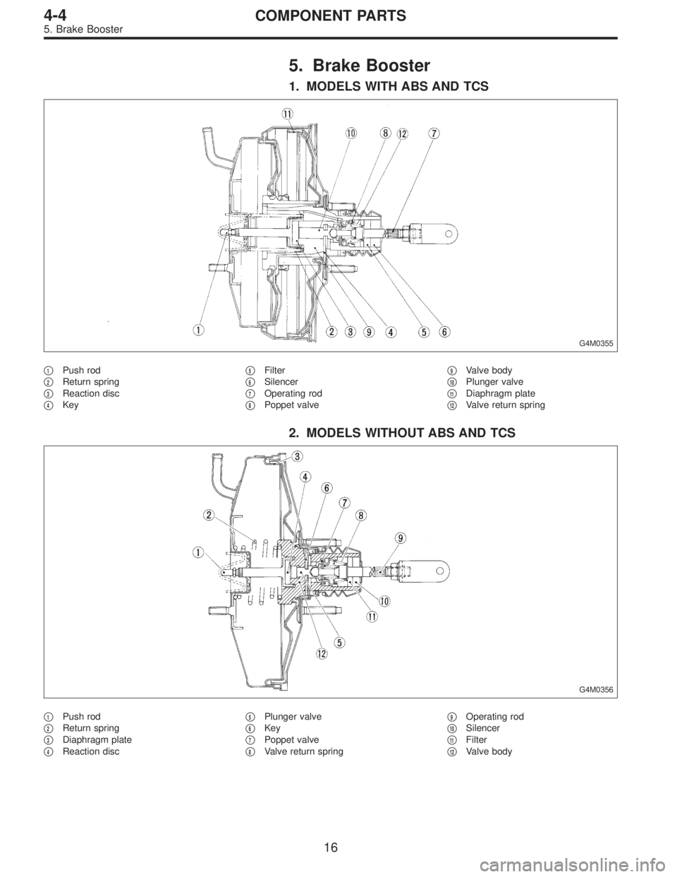
5. Brake Booster
1. MODELS WITH ABS AND TCS
G4M0355
�1Push rod
�
2Return spring
�
3Reaction disc
�
4Key�
5Filter
�
6Silencer
�
7Operating rod
�
8Poppet valve�
9Valve body
�
10Plunger valve
�
11Diaphragm plate
�
12Valve return spring
2. MODELS WITHOUT ABS AND TCS
G4M0356
�1Push rod
�
2Return spring
�
3Diaphragm plate
�
4Reaction disc�
5Plunger valve
�
6Key
�
7Poppet valve
�
8Valve return spring�
9Operating rod
�
10Silencer
�
11Filter
�
12Valve body
16
4-4COMPONENT PARTS
5. Brake Booster
Page 1365 of 3342
 Under the ABS sequence control, after the hydraulic
unit solenoid valve is driven, the operation of the hydraulic
unit can be checked by means of the brake tester or pres-
s")
D: ABS SEQUENCE CONTROL
1) Under the ABS sequence control, after the hydraulic
unit solenoid valve is driven, the operation of the hydraulic
unit can be checked by means of the brake tester or pres-
sure gauge.
2) ABS sequence control can be started by diagnosis con-
nector or select monitor.
B4M0082D
1. OPERATIONAL GUIDELINES OF THE ABS
SEQUENCE CONTROL WITH DIAGNOSIS
CONNECTOR
1) Connect diagnosis terminals to terminals No. 3 and No.
6 of the diagnosis connector beside driver’s seat heater
unit.
2) Set the speed of all wheels at 4 km/h (2 MPH) or less.
3) Turn ignition switch OFF.
4) Within 0.5 seconds after the ABS warning light goes
out, depress the brake pedal and hold it immediately after
ignition switch is turned to ON.
CAUTION:
Do not depress the clutch pedal.
NOTE:
�When the ignition switch is set to on, the brake pedal
must not be depressed.
�Engine must not operate.
5) After completion of ABS sequence control, turn ignition
switch OFF.
2. OPERATIONAL GUIDELINES OF THE ABS
SEQUENCE CONTROL WITH SELECT MONITOR
1) Connect select monitor to data link connector beside
driver’s seat heater unit.
2) Turn ignition switch ON.
3) Put select monitor to ABS mode.
B4M0635
4) PressFD1ENTkey.
83
4-4SERVICE PROCEDURE
15. Hydraulic Unit for ABS System (ABS 5.3 Type)
Page 1366 of 3342
B4M0997
5) The message shown in the figure is displayed.
B4M0998
6) The message shown in the figure is displayed as fol-
lows:
(1) When using the brake tester, depress brake pedal
with braking force of 981 N (100 kg, 221 lb).
(2) When using the pressure gauge, depress brake
pedal so as to make the pressure gauge indicate 3,432
kPa (35 kg/cm
2, 498 psi).
CAUTION:
Do not depress the clutch pedal.
B4M0999
7) When the message shown in the figure is displayed,
press ENT key.
8) Check points will be displayed on select monitor.
B4M1000
9) When ABS sequence control cannot be started (by sys-
tem malfunction, etc.), the message shown in the figure will
be displayed.
NOTE:
Read the trouble codes. Repair faulty parts.
B4M1030
10) After completion of ABS sequence control, turn ignition
switch OFF.
84
4-4SERVICE PROCEDURE
15. Hydraulic Unit for ABS System (ABS 5.3 Type)
Page 1367 of 3342
3. CONDITIONS FOR COMPLETION OF ABS
SEQUENCE CONTROL
When the following conditions develop, the ABS sequence
control stops and ABS operation is returned to the normal
control mode.
1) When the speed of at least one wheel reaches 10 km/h
(6 MPH).
2) When terminal No. 3 or No. 6 are separated from diag-
nosis terminals. (When select monitor is not used.)
3) When the brake pedal is released during sequence con-
trol and the braking lamp switch is set to off.
4) When brake pedal is depressed after ignition key is
turned to ON, and before ABS warning light goes out.
(When select monitor is not used.)
5) When brake pedal is not depressed after ignition key is
turned to ON, and within 0.5 seconds after ABS warning
light goes out. (When select monitor is not used.)
6) After completion of the sequence control.
7) When malfunction is detected. (When select monitor is
used.)
85
4-4SERVICE PROCEDURE
15. Hydraulic Unit for ABS System (ABS 5.3 Type)
Page 1368 of 3342
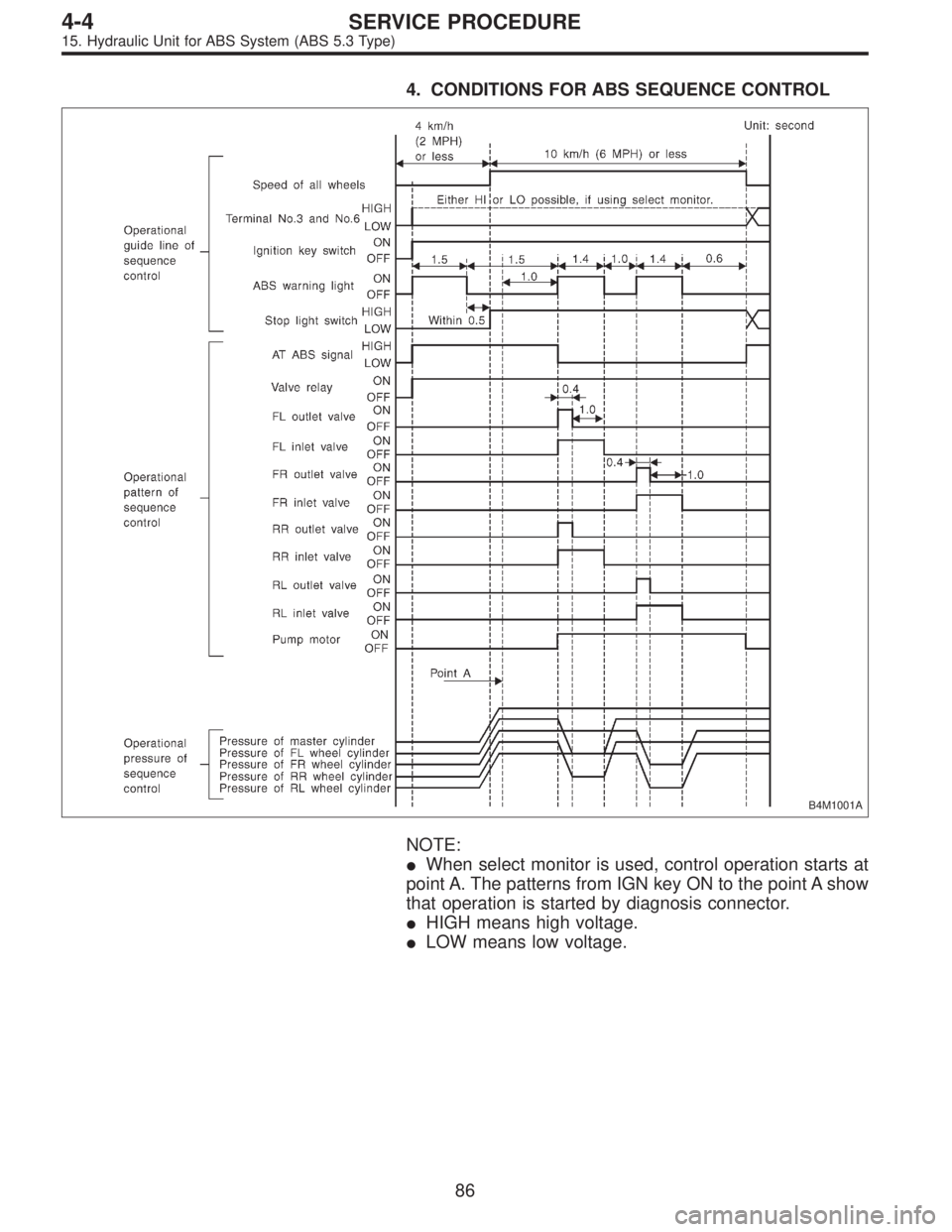
4. CONDITIONS FOR ABS SEQUENCE CONTROL
B4M1001A
NOTE:
�When select monitor is used, control operation starts at
point A. The patterns from IGN key ON to the point A show
that operation is started by diagnosis connector.
�HIGH means high voltage.
�LOW means low voltage.
86
4-4SERVICE PROCEDURE
15. Hydraulic Unit for ABS System (ABS 5.3 Type)
Page 1387 of 3342
B4M0622A
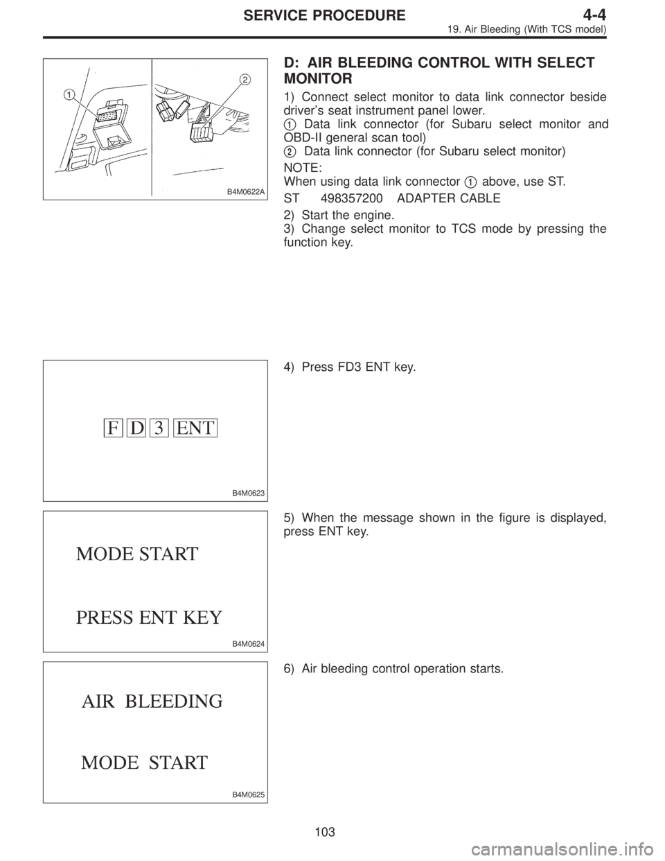
D: AIR BLEEDING CONTROL WITH SELECT
MONITOR
1) Connect select monitor to data link connector beside
driver’s seat instrument panel lower.
�
1Data link connector (for Subaru select monitor and
OBD-II general scan tool)
�
2Data link connector (for Subaru select monitor)
NOTE:
When using data link connector�
1above, use ST.
ST 498357200 ADAPTER CABLE
2) Start the engine.
3) Change select monitor to TCS mode by pressing the
function key.
B4M0623
4) Press FD3 ENT key.
B4M0624
5) When the message shown in the figure is displayed,
press ENT key.
B4M0625
6) Air bleeding control operation starts.
103
4-4SERVICE PROCEDURE
19. Air Bleeding (With TCS model)
 The message shown in the figure is displayed.
B4M0998
6) The message shown in the figure is displayed as fol-
lows:
(1) When using the brake tester, depress brake pedal
with braking force o")
 When the speed o")