Page 1739 of 3342
1. Precaution
�Before disassembling or reassembling parts, always
disconnect battery ground cable. When repairing
radio, control modules, etc. which are provided with
memory functions, record memory contents before
disconnecting battery ground cable. Otherwise, these
contents are cancelled upon disconnection.
�Reassemble parts in reverse order of disassembly
procedure unless otherwise indicated.
�Adjust parts to specifications contained in this
manual if so designated.
�Connect connectors and hoses securely during
reassembly.
�After reassembly, ensure functional parts operate
smoothly.
CAUTION:
�Airbag system wiring harness is routed near the
electrical parts and switch.
�All Airbag system wiring harness and connectors
are colored yellow. Do not use electrical test equip-
ment on these circuit.
�Be careful not to damage Airbag system wiring har-
ness when servicing the ignition key cylinder.
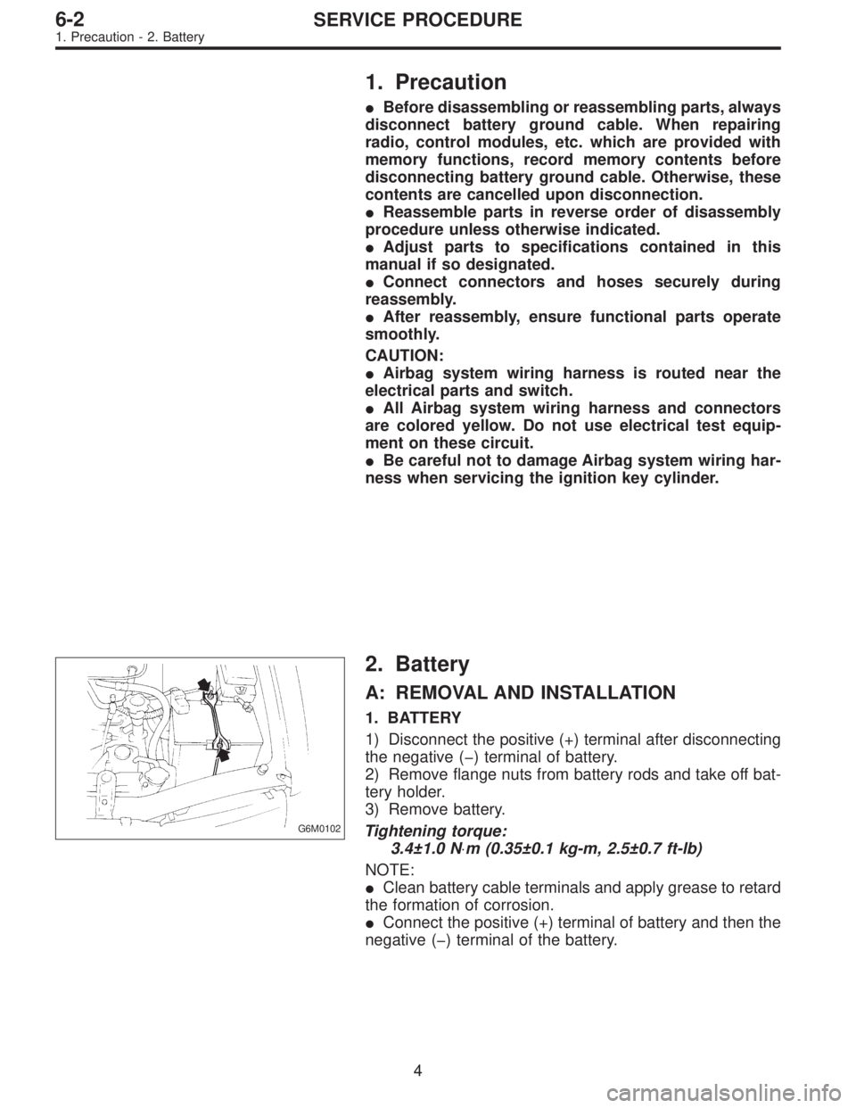
G6M0102
2. Battery
A: REMOVAL AND INSTALLATION
1. BATTERY
1) Disconnect the positive (+) terminal after disconnecting
the negative (�) terminal of battery.
2) Remove flange nuts from battery rods and take off bat-
tery holder.
3) Remove battery.
Tightening torque:
3.4±1.0 N⋅m (0.35±0.1 kg-m, 2.5±0.7 ft-lb)
NOTE:
�Clean battery cable terminals and apply grease to retard
the formation of corrosion.
�Connect the positive (+) terminal of battery and then the
negative (�) terminal of the battery.
4
6-2SERVICE PROCEDURE
1. Precaution - 2. Battery
Page 1740 of 3342
1. Precaution
�Before disassembling or reassembling parts, always
disconnect battery ground cable. When repairing
radio, control modules, etc. which are provided with
memory functions, record memory contents before
disconnecting battery ground cable. Otherwise, these
contents are cancelled upon disconnection.
�Reassemble parts in reverse order of disassembly
procedure unless otherwise indicated.
�Adjust parts to specifications contained in this
manual if so designated.
�Connect connectors and hoses securely during
reassembly.
�After reassembly, ensure functional parts operate
smoothly.
CAUTION:
�Airbag system wiring harness is routed near the
electrical parts and switch.
�All Airbag system wiring harness and connectors
are colored yellow. Do not use electrical test equip-
ment on these circuit.
�Be careful not to damage Airbag system wiring har-
ness when servicing the ignition key cylinder.
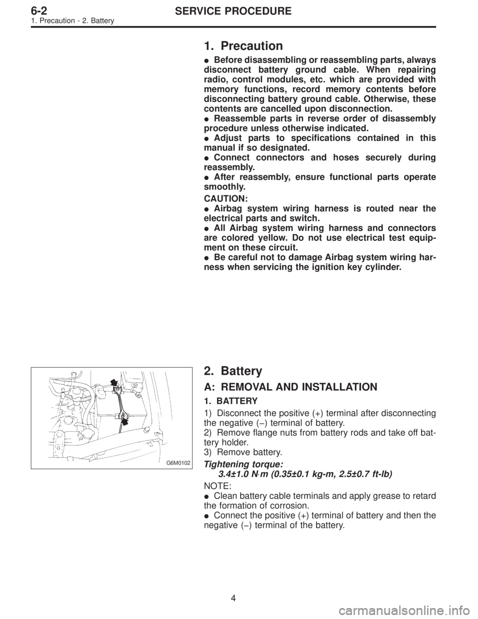
G6M0102
2. Battery
A: REMOVAL AND INSTALLATION
1. BATTERY
1) Disconnect the positive (+) terminal after disconnecting
the negative (�) terminal of battery.
2) Remove flange nuts from battery rods and take off bat-
tery holder.
3) Remove battery.
Tightening torque:
3.4±1.0 N⋅m (0.35±0.1 kg-m, 2.5±0.7 ft-lb)
NOTE:
�Clean battery cable terminals and apply grease to retard
the formation of corrosion.
�Connect the positive (+) terminal of battery and then the
negative (�) terminal of the battery.
4
6-2SERVICE PROCEDURE
1. Precaution - 2. Battery
Page 1745 of 3342
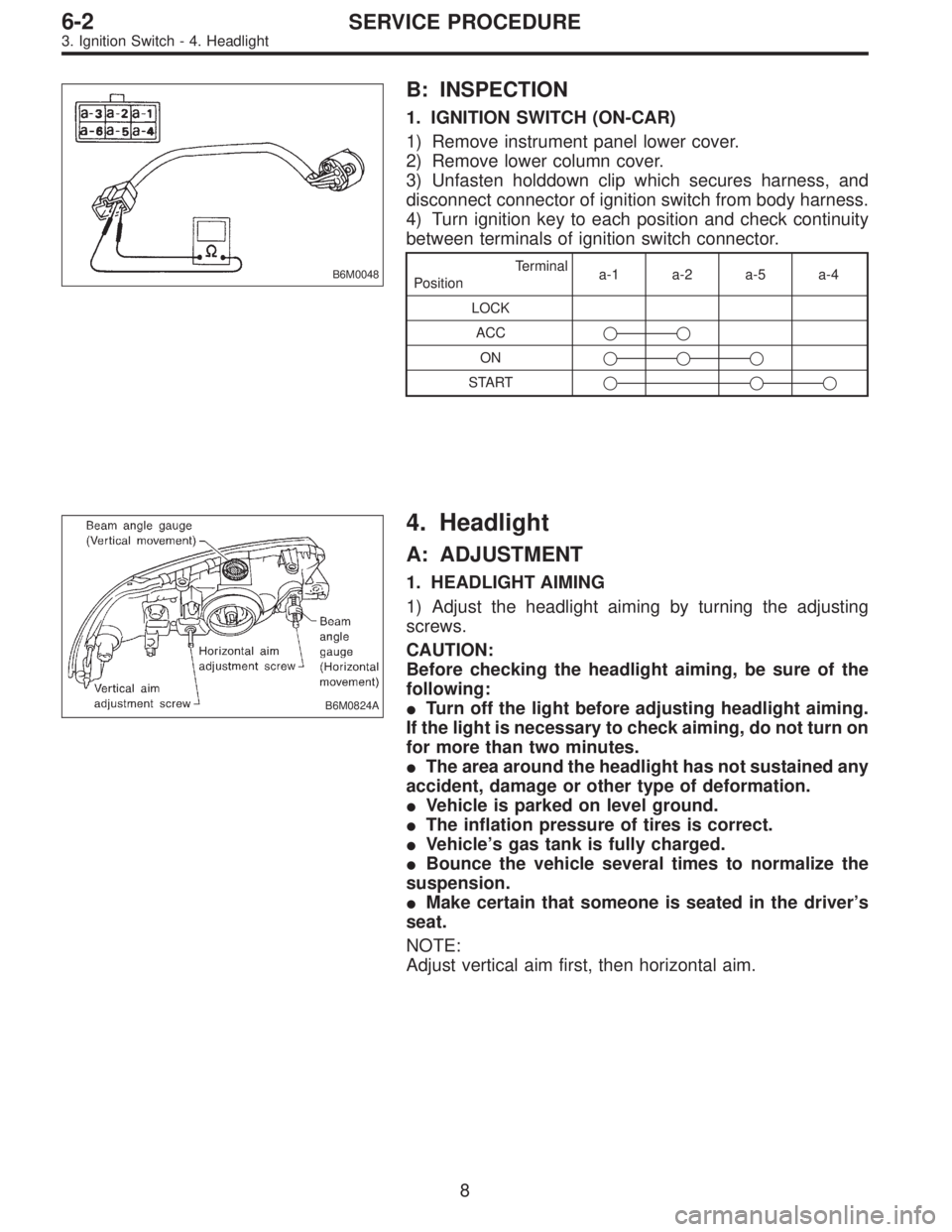
B6M0048
B: INSPECTION
1. IGNITION SWITCH (ON-CAR)
1) Remove instrument panel lower cover.
2) Remove lower column cover.
3) Unfasten holddown clip which secures harness, and
disconnect connector of ignition switch from body harness.
4) Turn ignition key to each position and check continuity
between terminals of ignition switch connector.
Terminal
Positiona-1 a-2 a-5 a-4
LOCK
ACC��
ON���
START���
B6M0824A
4. Headlight
A: ADJUSTMENT
1. HEADLIGHT AIMING
1) Adjust the headlight aiming by turning the adjusting
screws.
CAUTION:
Before checking the headlight aiming, be sure of the
following:
�Turn off the light before adjusting headlight aiming.
If the light is necessary to check aiming, do not turn on
for more than two minutes.
�The area around the headlight has not sustained any
accident, damage or other type of deformation.
�Vehicle is parked on level ground.
�The inflation pressure of tires is correct.
�Vehicle’s gas tank is fully charged.
�Bounce the vehicle several times to normalize the
suspension.
�Make certain that someone is seated in the driver’s
seat.
NOTE:
Adjust vertical aim first, then horizontal aim.
8
6-2SERVICE PROCEDURE
3. Ignition Switch - 4. Headlight
Page 1746 of 3342
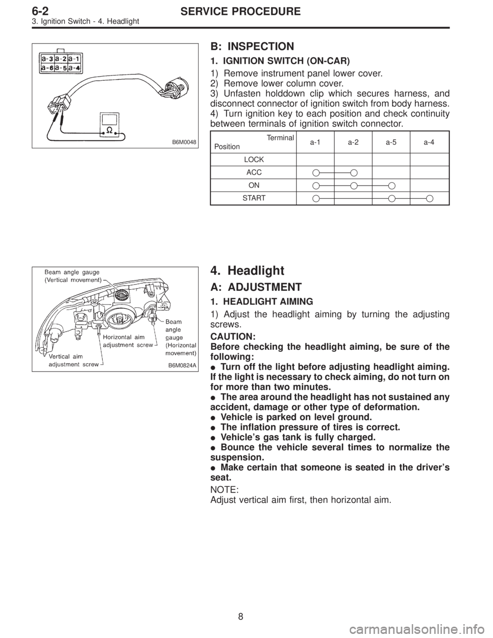
B6M0048
B: INSPECTION
1. IGNITION SWITCH (ON-CAR)
1) Remove instrument panel lower cover.
2) Remove lower column cover.
3) Unfasten holddown clip which secures harness, and
disconnect connector of ignition switch from body harness.
4) Turn ignition key to each position and check continuity
between terminals of ignition switch connector.
Terminal
Positiona-1 a-2 a-5 a-4
LOCK
ACC��
ON���
START���
B6M0824A
4. Headlight
A: ADJUSTMENT
1. HEADLIGHT AIMING
1) Adjust the headlight aiming by turning the adjusting
screws.
CAUTION:
Before checking the headlight aiming, be sure of the
following:
�Turn off the light before adjusting headlight aiming.
If the light is necessary to check aiming, do not turn on
for more than two minutes.
�The area around the headlight has not sustained any
accident, damage or other type of deformation.
�Vehicle is parked on level ground.
�The inflation pressure of tires is correct.
�Vehicle’s gas tank is fully charged.
�Bounce the vehicle several times to normalize the
suspension.
�Make certain that someone is seated in the driver’s
seat.
NOTE:
Adjust vertical aim first, then horizontal aim.
8
6-2SERVICE PROCEDURE
3. Ignition Switch - 4. Headlight
Page 1749 of 3342
![SUBARU LEGACY 1997 Service Repair Manual B6M0236
3. COMBINATION SWITCH (WITHOUT AIRBAG
MODEL)
Refer to 5-5 [W7A0] as for removal of combination
switch on airbag equipped model.
1) Remove steering wheel. <Ref. to 4-3 [W2A0].>
2) Remove screws SUBARU LEGACY 1997 Service Repair Manual B6M0236
3. COMBINATION SWITCH (WITHOUT AIRBAG
MODEL)
Refer to 5-5 [W7A0] as for removal of combination
switch on airbag equipped model.
1) Remove steering wheel. <Ref. to 4-3 [W2A0].>
2) Remove screws](/manual-img/17/57434/w960_57434-1748.png)
B6M0236
3. COMBINATION SWITCH (WITHOUT AIRBAG
MODEL)
Refer to 5-5 [W7A0] as for removal of combination
switch on airbag equipped model.
1) Remove steering wheel.
2) Remove screws which secure upper column cover to
lower column cover.
3) Remove screws which secure knee protector and
remove knee protector.
CAUTION:
When installing knee protector, ensure that harness is
not caught by adjacent parts.
4) Disconnect connector from body harness and undo
holddown band.
G6M0107
5) Remove screws which secure switch and remove
switch.
CAUTION:
During installation (with key interlock)
�When routing combination switch harness around
steering system, do not place it over key interlock
release knob.
�After installing lower column cover, ensure that key
interlock release knob is accessible.
B6M0237
C: DISASSEMBLY AND ASSEMBLY
1. COMBINATION SWITCH
1) Remove screws which secure slip ring to combination
switch, and remove slip ring.
G6M0109
2) Remove screws which secure lighting switch, wiper and
washer switch. Remove both switches.
Assembly is in the reverse order of disassembly.
11
6-2SERVICE PROCEDURE
4. Headlight
Page 1777 of 3342
14. Vehicle Speed Sensor 2
A: GENERAL PRECAUTIONS
1) Be careful not to drop or bump sensor as this may break
built-in magnet.
2) Drive key is designed to separate from vehicle speed
sensor 2. Be careful not to lose it or forget to install.
3) Vehicle speed sensor 2 is installed in part (which con-
tains bearings, etc., finished to a high degree of accuracy).
Do not allow foreign matter (filings, sand, etc.) to get into
it.
4) When checking output of vehicle speed sensor 2 as a
single unit, ensure test leads are connected to their correct
terminals. Failure to do this may damage internal IC.
5) Discard vehicle speed sensor 2 after removal; replace
with new one.
B: REMOVAL
CAUTION:
�Be careful when removing vehicle speed sensor 2
immediately after driving vehicle for a while, as tem-
perature around it is high.
�Before removing vehicle speed sensor 2, clean dirt,
etc. from surrounding areas. Take care not to allow
foreign matter to get into mounting hole.
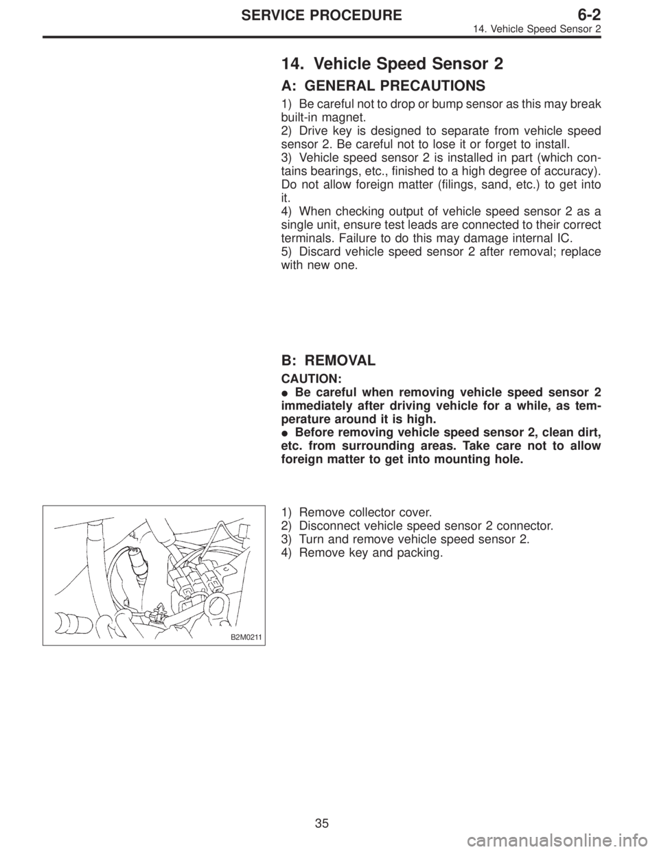
B2M0211
1) Remove collector cover.
2) Disconnect vehicle speed sensor 2 connector.
3) Turn and remove vehicle speed sensor 2.
4) Remove key and packing.
35
6-2SERVICE PROCEDURE
14. Vehicle Speed Sensor 2
Page 1778 of 3342
C: INSTALLATION
CAUTION:
�Ensure sensor mounting hole is clean and free of
foreign matter.
�Apply grease to tip end of key to prevent key from
falling off sensor.
�Align tip end of key with key groove on end of
speedometer shaft during installation.
1) Hand tighten vehicle speed sensor 2, then tighten it
using suitable tool.
Tightening torque required for sensor to reach bottom of
transmission is as follows:
Tightening torque:
0.39—0.88 N⋅m (4.0—9.0 kg-cm, 3.5—7.8 in-lb)
CAUTION:
�When torque must be applied that exceeds 0.88 N⋅m
(9.0 kg-cm, 7.8 in-lb), the key and key groove on end of
speedometer may not be aligned properly. Remove the
key, align it correctly and reassemble.
�Sensor threads are secured by Locktite. The reas-
sembly must be completed within 5 minutes before
Locktite dries.
2) Tighten vehicle speed sensor 2 further to specified
torque.
Tightening torque:
5.9±1.5 N⋅m (60±15 kg-cm, 52±13 in-lb)
36
6-2SERVICE PROCEDURE
14. Vehicle Speed Sensor 2
Page 1799 of 3342
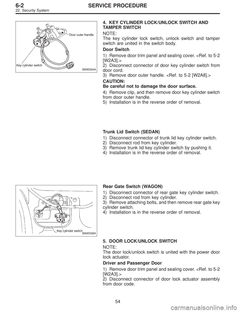
B6M0364A
4. KEY CYLINDER LOCK/UNLOCK SWITCH AND
TAMPER SWITCH
NOTE:
The key cylinder lock switch, unlock switch and tamper
switch are united in the switch body.
Door Switch
1) Remove door trim panel and sealing cover.
[W2A3].>
2) Disconnect connector of door key cylinder switch from
door cord.
3) Remove door outer handle.
CAUTION:
Be careful not to damage the door surface.
4) Remove clip, and then remove door key cylinder switch
from door outer handle.
5) Installation is in the reverse order of removal.
Trunk Lid Switch (SEDAN)
1) Disconnect connector of trunk lid key cylinder switch.
2) Disconnect rod from key cylinder.
3) Remove trunk lid key cylinder switch by pushing it.
4) Installation is in the reverse order of removal.
B6M0368A
Rear Gate Switch (WAGON)
1) Disconnect connector of rear gate key cylinder switch.
2) Disconnect rod from key cylinder.
3) Remove attaching bolts, and then remove rear gate key
cylinder switch.
4) Installation is in the reverse order of removal.
5. DOOR LOCK/UNLOCK SWITCH
NOTE:
The door lock/unlock switch is united with the power door
lock actuator.
Driver and Passenger Door
1) Remove door trim panel and sealing cover.
[W2A3].>
2) Disconnect connector of door lock actuator assembly
from door code.
54
6-2SERVICE PROCEDURE
22. Security System