Page 1544 of 3342
G5M0144
2. Trunk Lid
A: REMOVAL
1. TRUNK LID
1) Open trunk lid.
2) Remove trunk lid mounting bolts and detach trunk lid
from hinges.
G5M0145
2. TORSION BAR
1) Open trunk lid. Remove torsion bars from hinge links
using ST.
ST 927780000 REMOVER
CAUTION:
Be careful because torsion bar quickly swings back
when released.
2) Remove the left and right torsion bars.
WARNING:
Be careful because trunk lid drops under its own
weight when torsion bars are removed.
G5M0146
3. TRUNK LID LOCK ASSEMBLY AND KEY
CYLINDER
1) Remove rod of lock assembly from rod holder of key
lock assembly.
2) Remove nuts which hold lock assembly and remove
lock assembly.
NOTE:
�Always remove rear skirt trim panel beforehand, if so
equipped.
�Be careful not to bend opener cable.
B5M0269A
3) Remove rod holder and detach key cylinder from trunk
lid.
35
5-1SERVICE PROCEDURE
2. Trunk Lid
Page 1589 of 3342
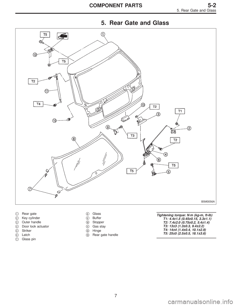
5. Rear Gate and Glass
B5M0056A
�1Rear gate
�
2Key cylinder
�
3Outer handle
�
4Door lock actuator
�
5Striker
�
6Latch
�
7Glass pin�
8Glass
�
9Buffer
�
10Stopper
�
11Gas stay
�
12Hinge
�
13Rear gate handle
Tightening torque: N⋅m (kg-m, ft-lb)
T1: 4.4±1.5 (0.45±0.15, 3.3±1.1)
T2: 7.4±2.0 (0.75±0.2, 5.4±1.4)
T3: 13±3 (1.3±0.3, 9.4±2.2)
T4: 14±4 (1.4±0.4, 10.1±2.9)
T5: 25±5 (2.5±0.5, 18.1±3.6)
7
5-2COMPONENT PARTS
5. Rear Gate and Glass
Page 1594 of 3342

1. Procedure Chart for Removing and
Installing Door and Related Parts
NOTE:
This flow chart shows the main procedures for removing
and installing the door and its related parts. For details,
refer to the text.
DoorDoor lock systemDoor regulator
�
Door glass
�
Remove door trim parts, etc.
�
REMOVALRemove front and rear upper stoppers
and stabilizer (inner).
�
Remove door.Disconnect joints
between latch, outer
handle, key lock and
remote assembly.Separate door glass from regulator.
Remove guide
channel B.Remove door
glass.
Remove door
lock system.Remove
regulator.
Install door.Install door
lock system.Install regulator.
Install guide
channel.Insert door glass.
�
Adjust door alignment.Adjust door
lock system.Mount door glass on regulator.
�
INSTALLATION
AND
ADJUSTMENTAdjust striker.Link latch, outer handle,
key lock and remote
assembly together.Install front and rear upper stoppers
and stabilizer (inner).
�
Adjust glass position.
��
Install door trim parts, etc.
���
Confirm.
�
�
���
��
��
���
��
���
���
�
�
�
12
5-2SERVICE PROCEDURE
1. Procedure Chart for Removing and Installing Door and Related Parts
Page 1599 of 3342
7. DOOR LATCH
1) Remove trim panel.
2) Remove inner remote assembly.
3) Remove sealing cover around latch service hole.
to 5-2 [W2A3].>
4) Completely close door glass.
B5M0067
5) Remove latch and actuator assembly.
(1) Turn rod holder to disconnect joint between key
lock and rod.
(2) Turn rod holder to disconnect joint between outer
handle and rod.
(3) Turn rod holder to disconnect joint between crank
and rod.
G5M0396
6) Loosen screws securing both latch and actuator, then
remove latch and actuator assembly through service hole
in bottom.
Tightening torque (screw):
6.4±2.0 N⋅m (0.65±0.2 kg-m, 4.7±1.4 ft-lb)
7) Installation is in the reverse order of removal.
Some special items will be described below.
8) Check operation of each part.
9) Check each sliding part for proper lubrication.
CAUTION:
After installation, be sure lock mechanism operates
normally.
17
5-2SERVICE PROCEDURE
2. Door
Page 1600 of 3342
B5M0068
8. OUTER HANDLE
1) Remove trim panel.
2) Remove sealing cover.
3) Detach door latch rod from outer handle and key lock.
4) Loosen nut securing outer handle and then remove
outer handle from outside.
CAUTION:
Be careful not to damage door.
Installation is in the reverse order of removal.
Tightening torque:
7.4±2.0 N⋅m (0.75±0.2 kg-m, 5.4±1.4 ft-lb)
B5M0069A
9. KEY LOCK
1) Remove trim panel.
2) Remove sealing cover.
3) Completely close door glass.
4) Remove outer handle.
5) Loosen spring�
1securing key lock.
6) Remove key lock from outer handle.
Installation is in the reverse order of removal.
NOTE:
Install so that key slot in key lock comes to center of hole
in outer handle.
B5M0070A
10. GUSSET
NOTE:
Be sure window is all the way down.
1) Remove trim panel.
2) Remove door rearview mirror.
3) Remove sealing cover.
4) Remove bolts and nuts which secure gusset.
5) Lift out gusset�
1.
To install, reverse the above removal procedures.
18
5-2SERVICE PROCEDURE
2. Door
Page 1608 of 3342
4. REAR DOOR GLASS
Alignment of rear door glass is basically the same as for
the front door glass. Due to slight difference in adjustment
dimensions for fore-aft, up-down, and in-out alignments,
key points for rear door adjustment are described below.
B5M0078A
B5M0074A
�Fore-aft adjustment
1) Door glass alignment must be adjusted so that glass-
to-center pillar fit is equal at all points. Always use dimen-
sions (indicated in figure) as a guide during adjustment.
NOTE:
If dimensions are smaller than those indicated, glass will be
caught in weatherstrip and may not raise to the fully closed
position.
2) After making fore-aft adjustment, raise and lower glass
to ensure it is free from any binding.
26
5-2SERVICE PROCEDURE
2. Door
Page 1611 of 3342
 General precautions in handling rear gate gas stay.
CAUTION:
�Do not attempt to disassemble gas stay because its
cylinder is filled with gas.
�Before discarding gas stay, place it at a slig")
G5M0551
9) General precautions in handling rear gate gas stay.
CAUTION:
�Do not attempt to disassemble gas stay because its
cylinder is filled with gas.
�Before discarding gas stay, place it at a slight angle
with the cylinder body side facing up and drilla2to3
mm (0.08 to 0.12 in) dia. hole to completely discharge
the content. (Gas is odorless, colorless and harmless;
however, metal powder may come out of the hole.)
G5M0491
�It is good practice to place a vinyl sack over it before
drilling the hole because oil may spurt out. Be careful
to prevent vinyl cover from becoming entangled on the
drill.
�Be careful not to scratch the exposed section of
piston rod or allow oil or paint to come in contact with
it.
�Do not attempt to rotate the extended piston rod.
10) Installation is in the reverse order of removal.
CAUTION:
�Be sure to add sealer to hinge.
�When installing rear gate, be careful not to damage
coating on body and rear gate.
G5M0404
2. LATCH
1) Remove trim panel.
2) Disengage rod from holder (= key cylinder).
3) Remove bolts from auto-door lock actuator.
4) Remove bolts from latch, and detach latch.
5) Disconnect rear gate switch connector.
6) Disconnect auto-door lock actuator connector.
7) Detach latch.
8) Installation is in the reverse order of removal.
B5M0083
3. OUTER HANDLE
1) Remove trim panel.
2) Disconnect rod from outer handle.
3) Remove two nuts used to hold outer handle to the
inside of rear gate, and detach outer handle.
CAUTION:
Be careful not to damage packing when removing
outer handle.
4) Installation is in the reverse order of removal.
29
5-2SERVICE PROCEDURE
3. Rear Gate
Page 1612 of 3342
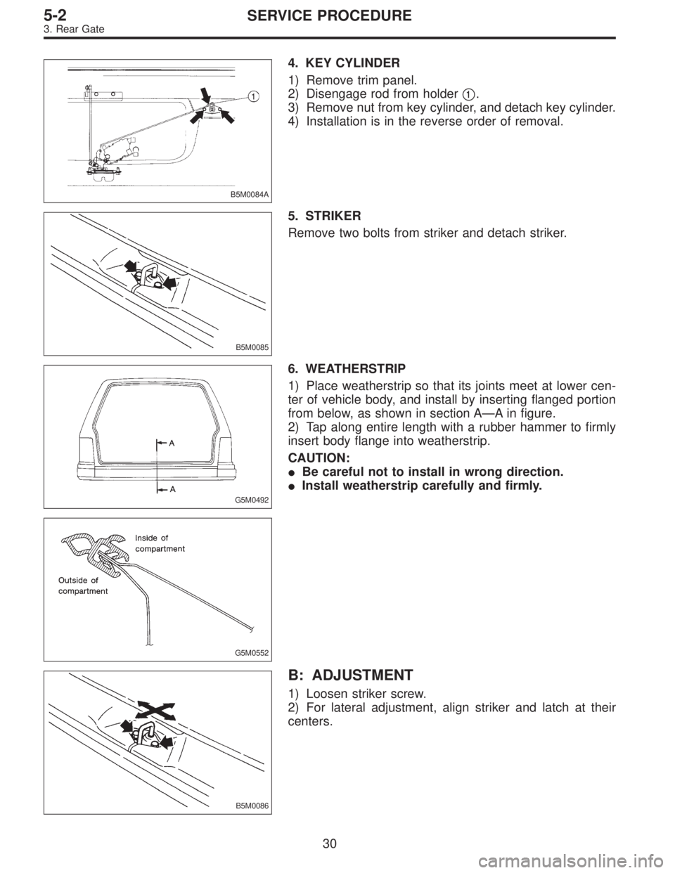
B5M0084A
4. KEY CYLINDER
1) Remove trim panel.
2) Disengage rod from holder�
1.
3) Remove nut from key cylinder, and detach key cylinder.
4) Installation is in the reverse order of removal.
B5M0085
5. STRIKER
Remove two bolts from striker and detach striker.
G5M0492
6. WEATHERSTRIP
1) Place weatherstrip so that its joints meet at lower cen-
ter of vehicle body, and install by inserting flanged portion
from below, as shown in section A—A in figure.
2) Tap along entire length with a rubber hammer to firmly
insert body flange into weatherstrip.
CAUTION:
�Be careful not to install in wrong direction.
�Install weatherstrip carefully and firmly.
G5M0552
B5M0086
B: ADJUSTMENT
1) Loosen striker screw.
2) For lateral adjustment, align striker and latch at their
centers.
30
5-2SERVICE PROCEDURE
3. Rear Gate
 Open trunk lid.
2) Remove trunk lid mounting bolts and detach trunk lid
from hinges.
G5M0145
2. TORSION BAR
1) Open trunk lid. Remove torsion bars from")
![SUBARU LEGACY 1997 Service Repair Manual 7. DOOR LATCH
1) Remove trim panel. <Ref. to 5-2 [W2A2].>
2) Remove inner remote assembly. <Ref. to 5-2 [W2A6].>
3) Remove sealing cover around latch service hole. <Ref.
to 5-2 [W2A3].>
4) Completely](/manual-img/17/57434/w960_57434-1598.png "SUBARU LEGACY 1997 Service Repair Manual 7. DOOR LATCH
1) Remove trim panel. <Ref. to 5-2 [W2A2].>
2) Remove inner remote assembly. <Ref. to 5-2 [W2A6].>
3) Remove sealing cover around latch service hole. <Ref.
to 5-2 [W2A3].>
4) Completely")
![SUBARU LEGACY 1997 Service Repair Manual B5M0068
8. OUTER HANDLE
1) Remove trim panel. <Ref. to 5-2 [W2A2].>
2) Remove sealing cover. <Ref. to 5-2 [W2A3].>
3) Detach door latch rod from outer handle and key lock.
4) Loosen nut securing outer](/manual-img/17/57434/w960_57434-1599.png "SUBARU LEGACY 1997 Service Repair Manual B5M0068
8. OUTER HANDLE
1) Remove trim panel. <Ref. to 5-2 [W2A2].>
2) Remove sealing cover. <Ref. to 5-2 [W2A3].>
3) Detach door latch rod from outer handle and key lock.
4) Loosen nut securing outer")