Page 1394 of 3342
B4M0635
4) Press FD1 ENT key.
B4M0634
5) The message shown in the figure is displayed as fol-
lows:
(1) When using the brake tester, depress brake pedal
with braking force of 981 to 1,471 N (100 to 150 kg, 221
to 331 lb).
(2) When using the pressure gauge, depress brake
pedal so as to make the pressure gauge indicate 3,432
kPa (35 kg/cm
2, 498 psi)
B4M0624
6) When the message shown in the figure is displayed,
press ENT key.
7) Checked portions will be displayed on select monitor.
B4M0627
8) When ABS sequence control cannot be started (by sys-
tem malfunction, etc.), the message shown in the figure will
be displayed.
NOTE:
Read the trouble codes. Repair faulty parts.
9) After completion of ABS sequence control, turn ignition
switch OFF.
11 0
4-4SERVICE PROCEDURE
20. Hydraulic Unit for ABS/TCS System
Page 1396 of 3342
4. CONDITIONS FOR ABS SEQUENCE CONTROL
B4M0637A
NOTE:
When select monitor is used, control operation starts at
point A. It is not required to operate brake lamp switch for
starting ABS sequence control operation. The patterns
from IGN key ON to the point A show that operation is
started by diagnosis connector.
11 2
4-4SERVICE PROCEDURE
20. Hydraulic Unit for ABS/TCS System
Page 1400 of 3342
2. OPERATIONAL GUIDELINES OF THE TCS
SEQUENCE CONTROL WITH SELECT MONITOR
1) Connect select monitor to data link connector beside
driver’s seat heater unit.
2) Engine starts.
3) Put select monitor to TCS mode.
4) Put select monitor to FBI mode. Make sure code 11 is
indicated.
NOTE:
When trouble codes are stored in memory, repair the faulty
parts.
B4M0639
5) Press FD2 ENT key.
B4M0624
6) When the message shown in the figure is displayed,
press ENT key.
7) Checked portions will be displayed on select monitor.
B4M0627
8) When TCS sequence control cannot be started (by sys-
tem malfunction, etc.), the message shown in the figure will
be displayed.
NOTE:
Read the trouble codes. Repair faulty parts.
11 6
4-4SERVICE PROCEDURE
20. Hydraulic Unit for ABS/TCS System
Page 1402 of 3342
4. CONDITIONS FOR TCS SEQUENCE CONTROL
B4M0642A
NOTE:
When select monitor is used, control operation starts at
point A. It is not required to operate TCS OFF switch for
starting control operation. The patterns from IGN key ON
to point A show operation is started by diagnosis connec-
tor.
11 8
4-4SERVICE PROCEDURE
20. Hydraulic Unit for ABS/TCS System
Page 1412 of 3342
B4M0635
4) PressFD1ENTkey.
B4M0997
5) The message shown in the figure is displayed.
B4M0998
6) The message shown in the figure is displayed as fol-
lows:
(1) When using the brake tester, depress brake pedal
with braking force of 981 N (100 kg, 221 lb).
(2) When using the pressure gauge, depress brake
pedal so as to make the pressure gauge indicate 3,432
kPa (35 kg/cm
2, 498 psi).
CAUTION:
Do not depress the clutch pedal.
B4M0999
7) When the message shown in the figure is displayed,
press ENT key.
8) Check points will be displayed on select monitor.
B4M1000
9) When ABS sequence control cannot be started (by sys-
tem malfunction, etc.), the message shown in the figure will
be displayed.
NOTE:
Read the trouble codes. Repair faulty parts.
127
4-4SERVICE PROCEDURE
22. ABS Control Module and Hydraulic Control Unit (ABSCM&H/U) (ABS 5.3i Type)
Page 1413 of 3342
 After completion of ABS sequence control.
H4M1144
11) Press 0 key to start ABS sequence control again and
press 1 key to end.
3. CONDITIONS FOR COMPLETION OF ABS
SEQUENCE CONTROL
When the")
B4M1030
10) After completion of ABS sequence control.
H4M1144
11) Press 0 key to start ABS sequence control again and
press 1 key to end.
3. CONDITIONS FOR COMPLETION OF ABS
SEQUENCE CONTROL
When the following conditions develop, the ABS sequence
control stops and ABS operation is returned to the normal
control mode.
1) When the speed of at least one wheel reaches 10 km/h
(6 MPH).
2) When terminal No. 3 or No. 6 are separated from diag-
nosis terminals. (When select monitor is not used.)
3) When the brake pedal is released during sequence con-
trol and the braking lamp switch is set to off.
4) When brake pedal is depressed after ignition key is
turned to ON, and before ABS warning light goes out.
(When select monitor is not used.)
5) When brake pedal is not depressed after ignition key is
turned to ON, and within 0.5 seconds after ABS warning
light goes out. (When select monitor is not used.)
6) After completion of the sequence control.
7) When malfunction is detected. (When select monitor is
used.)
128
4-4SERVICE PROCEDURE
22. ABS Control Module and Hydraulic Control Unit (ABSCM&H/U) (ABS 5.3i Type)
Page 1414 of 3342
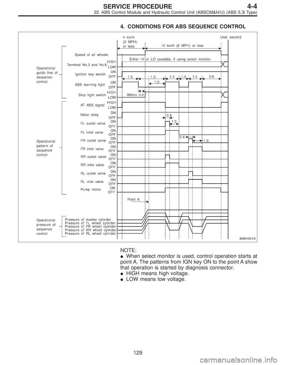
4. CONDITIONS FOR ABS SEQUENCE CONTROL
B4M1001A
NOTE:
�When select monitor is used, control operation starts at
point A. The patterns from IGN key ON to the point A show
that operation is started by diagnosis connector.
�HIGH means high voltage.
�LOW means low voltage.
129
4-4SERVICE PROCEDURE
22. ABS Control Module and Hydraulic Control Unit (ABSCM&H/U) (ABS 5.3i Type)
Page 1478 of 3342
 Begin at the connection of the low-pressure tube to the
evaporator, and work your way along the low-pressure of
the system to the compressor. There are thre")
G4M0615
5. LEAK TEST—LOW-PRESSURE SIDE
1) Begin at the connection of the low-pressure tube to the
evaporator, and work your way along the low-pressure of
the system to the compressor. There are three places to
check on each tube connection.
2) Check the area.
(1) Check the area where the fitting joins the tube.
(2) Check the area where the two parts of the fitting
join each other.
G4M0616
(3) Check the area where the nut joins the tube.
G4M0617
6. CHECK THE FLEXIBLE HOSES
Visually inspect the rubber portions of the flexible hoses for
cracking. Probe the rubber section, including the ends of
any insulators or protectors which may cover sections of
the rubber hose, and near the ends where the rubber
meets the metal collar.
NOTE:
Be certain to move the probe slowly [approximately 25 mm
(1 in) per second] when probing along any length of hose
or tube.
G4M0618
7. CHECK THE EVAPORATOR ASSEMBLY
1) Use one or both of the following methods to check the
evaporator assembly.
2) Remove the drain hose from the case drain nipple. Hold
the probe at the end of the case drain nipple for at least 10
seconds. Be certain to reconnect the drain hose when fin-
ished.
3) With the ignition key in the“ACC”position, run the
blower on high speed for 1 minute, then turn the blower off.
Place the probe in the center instrument panel vent, an turn
the blower on low speed for 1 to 2 seconds, then turn the
blower off. Leave the probe in the vent for at least 10 sec-
onds.
25
4-7SERVICE PROCEDURE
8. Leak Testing
 Press FD1 ENT key.
B4M0634
5) The message shown in the figure is displayed as fol-
lows:
(1) When using the brake tester, depress brake pedal
with braking force of 981 to 1,471 N (100 to 15")

![SUBARU LEGACY 1997 Service Repair Manual 2. OPERATIONAL GUIDELINES OF THE TCS
SEQUENCE CONTROL WITH SELECT MONITOR
1) Connect select monitor to data link connector beside
driver’s seat heater unit. <Ref. to 4-4 [W19D0] step 1).>
2) Engine](/manual-img/17/57434/w960_57434-1399.png "SUBARU LEGACY 1997 Service Repair Manual 2. OPERATIONAL GUIDELINES OF THE TCS
SEQUENCE CONTROL WITH SELECT MONITOR
1) Connect select monitor to data link connector beside
driver’s seat heater unit. <Ref. to 4-4 [W19D0] step 1).>
2) Engine")

 PressFD1ENTkey.
B4M0997
5) The message shown in the figure is displayed.
B4M0998
6) The message shown in the figure is displayed as fol-
lows:
(1) When using the brake tester, depress brake")