Page 196 of 3342
![SUBARU LEGACY 1997 Service Repair Manual
4-4d
RIonGS1
BRAKES
[ABS
5
.31
TYPE]
10
.
Diagnostics
Chart
with
Select
Monitor
FR
(
FES
)
0
km/
h
84M0977
FL(FE6)
0
km/
h
B4M0978
RR
(
FE7
)
0
km/
h
84M0379
RL
(FE8)
0
km/
h
84M0980
G-](/manual-img/17/57434/w960_57434-195.png "SUBARU LEGACY 1997 Service Repair Manual
4-4d
RIonGS1
BRAKES
[ABS
5
.31
TYPE]
10
.
Diagnostics
Chart
with
Select
Monitor
FR
(
FES
)
0
km/
h
84M0977
FL(FE6)
0
km/
h
B4M0978
RR
(
FE7
)
0
km/
h
84M0379
RL
(FE8)
0
km/
h
84M0980
G-")
4-4d
RIonGS1
BRAKES
[ABS
5
.31
TYPE]
10
.
Diagnostics
Chart
with
Select
Monitor
FR
(
FES
)
0
km/
h
84M0977
FL(FE6)
0
km/
h
B4M0978
RR
(
FE7
)
0
km/
h
84M0379
RL
(FE8)
0
km/
h
84M0980
G-SENS
(FE14)
3
.70
V
B4M0981
10AG6
CHECK
FREEZE
FRAME
DATA
.
1)
Press
[F],
[E]
and
[5]
on
the
select
monitor
.
2)
Read
the
select
monitor
display
.
CHECK
:
Is
the
reading
indicated
on
monitor
display0
km?
C,rES~
:
Go
tostep
10AG7
.
No
:
Go
tostep
10AG15
.
1
10AG7
I
CHECK
FREEZE
FRAME
DATA
.
1)
Press
the
scroll
keyso
that
FE6
appears
on
the
moni-
tor
display
.
2)
Read
the
select
monitor
display
.
CHECK
:
Is
the
reading
indicated
on
monitor
display
0
km?
~
:
Go
to
step
10AG8
.
No
:
Go
to
step
10AG15
.
J
10AG8
I
CHECK
FREEZE
FRAME
DATA
.
1)
Press
the
scroll
key
so
that
FE7
appears
on
the
moni-
tor
display
.
2)
Read
the
select
monitor
display
.
ELK
:
Is
the
reading
indicated
on
monitor
display0
km?
Go
tostep
10AG9
.
No
:
Go
tostep
10AG15
.
10AG9
CHECK
FREEZE
FRAME
DATA
.
1)
Press
the
scroll
keyso
that
FE8
appears
on
the
moni-
tor
display
.
2)
Read
the
select
monitor
display
.
ECK
:
Is
the
reading
indicated
on
monitor
display0
km?
Go
to
step
10AG10
.
No
:
Go
to
step
10AG15
.
1
10AG10
I
CHECK
FREEZE
FRAME
DATA
.
1)
Press
the
scroll
keyso
that
FE14
appears
on
the
mon-
itor
display
.
2)
Read
the
select
monitor
display
.
CHECK
:
Is
the
reading
indicated
on
monitor
display
more
than3
.65
V?
Go
to
step
10AG11
.
No
:
Go
to
step
10AG15
.
188
Page 269 of 3342
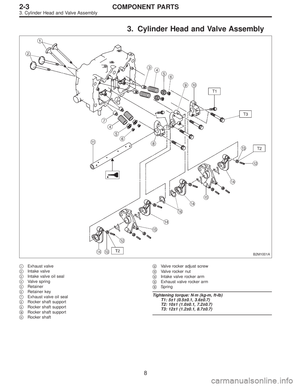
3. Cylinder Head and Valve Assembly
B2M1001A
�1Exhaust valve
�
2Intake valve
�
3Intake valve oil seal
�
4Valve spring
�
5Retainer
�
6Retainer key
�
7Exhaust valve oil seal
�
8Rocker shaft support
�
9Rocker shaft support
�
10Rocker shaft support
�
11Rocker shaft�
12Valve rocker adjust screw
�
13Valve rocker nut
�
14Intake valve rocker arm
�
15Exhaust valve rocker arm
�
16Spring
Tightening torque: N⋅m (kg-m, ft-lb)
T1: 5±1 (0.5±0.1, 3.6±0.7)
T2: 10±1 (1.0±0.1, 7.2±0.7)
T3: 12±1 (1.2±0.1, 8.7±0.7)
8
2-3COMPONENT PARTS
3. Cylinder Head and Valve Assembly
Page 271 of 3342
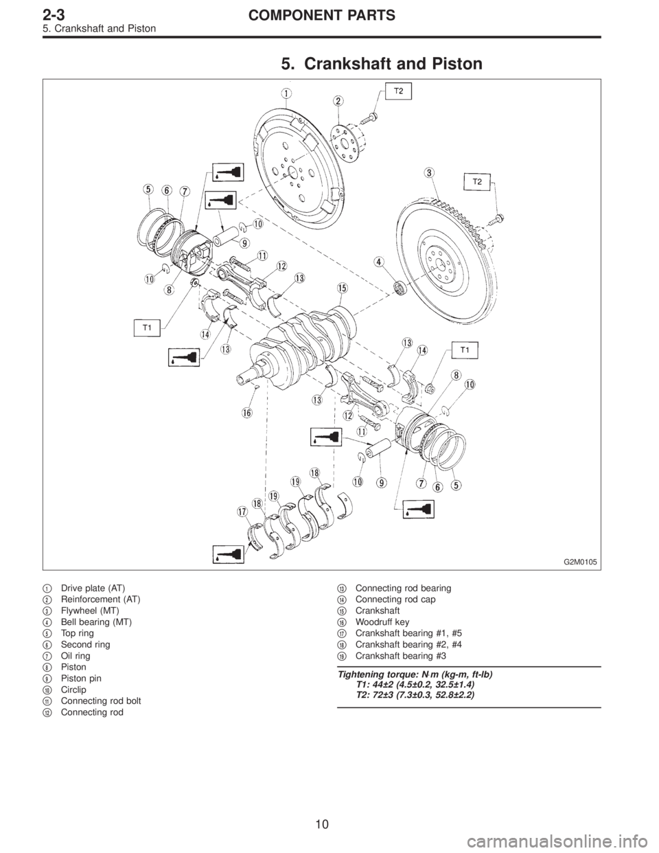
5. Crankshaft and Piston
G2M0105
�1Drive plate (AT)
�
2Reinforcement (AT)
�
3Flywheel (MT)
�
4Bell bearing (MT)
�
5Top ring
�
6Second ring
�
7Oil ring
�
8Piston
�
9Piston pin
�
10Circlip
�
11Connecting rod bolt
�
12Connecting rod�
13Connecting rod bearing
�
14Connecting rod cap
�
15Crankshaft
�
16Woodruff key
�
17Crankshaft bearing #1, #5
�
18Crankshaft bearing #2, #4
�
19Crankshaft bearing #3
Tightening torque: N⋅m (kg-m, ft-lb)
T1: 44±2 (4.5±0.2, 32.5±1.4)
T2: 72±3 (7.3±0.3, 52.8±2.2)
10
2-3COMPONENT PARTS
5. Crankshaft and Piston
Page 283 of 3342
B2M0108A
3) Measure the extension of rod beyond the body. If it is
not within specifications, replace with a new one.
Rod extension: H
15.4 — 16.4 mm (0.606 — 0.646 in)
3. BELT TENSIONER
1) Check mating surfaces of timing belt and contact point
of tension adjuster rod for abnormal wear or scratches.
Replace belt tensioner if faulty.
2) Check spacer and tensioner bushing for wear.
3) Check tensioner for smooth rotation. Replace if noise or
excessive play is noted.
4) Check tensioner for grease leakage.
4. BELT IDLER
1) Check idler for smooth rotation. Replace if noise or
excessive play is noted.
2) Check outer contacting surfaces of idler pulley for
abnormal wear and scratches.
3) Check idler for grease leakage.
5. SPROCKET
1) Check sprocket teeth for abnormal wear and scratches.
2) Make sure there is no free play between sprocket and
key.
3) Check crankshaft sprocket notch for sensor for damage
and contamination of foreign matter.
21
2-3SERVICE PROCEDURE
3. Timing Belt
Page 303 of 3342
B: DISASSEMBLY
B2M0121A
1) Remove rocker cover.
2) Remove valve rocker assembly.
3) Remove camshaft and support.
4) Place cylinder head on ST.
ST 498267200 CYLINDER HEAD TABLE
B2M0386A
5) Set ST on valve spring. Compress valve spring and
remove the valve spring retainer key. Remove each valve
and valve spring.
ST 499718000 VALVE SPRING REMOVER
CAUTION:
�Mark each valve to prevent confusion.
�Use extreme care not to damage the lips of the
intake valve oil seals and exhaust valve oil seals.
6) Removal of plug (cylinder head LH)
CAUTION:
Do not remove plug unless necessary.
40
2-3SERVICE PROCEDURE
6. Cylinder Head
Page 310 of 3342
B2M0386A
(3) Install valve spring and retainer.
CAUTION:
Be sure to install the valve springs with their painted
facing towards the valve spring retainer.
(4) Set ST on valve spring.
ST 499718000 VALVE SPRING REMOVER
(5) Compress valve spring and fit valve spring retainer
key.
B2M1210A
(6) After installing, tap valve spring retainers lightly
with wooden hammer for better seating.
3) Install camshaft and support.
4) Install valve rocker assembly.
5) Install rocker cover.
47
2-3SERVICE PROCEDURE
6. Cylinder Head
Page 349 of 3342
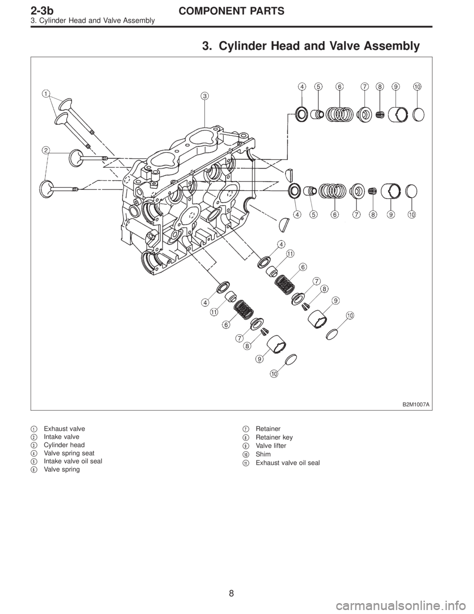
3. Cylinder Head and Valve Assembly
B2M1007A
�1Exhaust valve
�
2Intake valve
�
3Cylinder head
�
4Valve spring seat
�
5Intake valve oil seal
�
6Valve spring�
7Retainer
�
8Retainer key
�
9Valve lifter
�
10Shim
�
11Exhaust valve oil seal
8
2-3bCOMPONENT PARTS
3. Cylinder Head and Valve Assembly
Page 351 of 3342
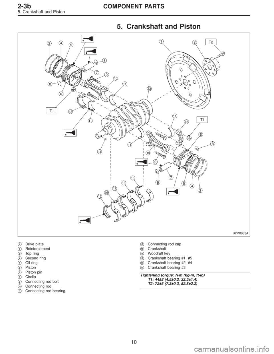
5. Crankshaft and Piston
B2M0683A
�1Drive plate
�
2Reinforcement
�
3Top ring
�
4Second ring
�
5Oil ring
�
6Piston
�
7Piston pin
�
8Circlip
�
9Connecting rod bolt
�
10Connecting rod
�
11Connecting rod bearing�
12Connecting rod cap
�
13Crankshaft
�
14Woodruff key
�
15Crankshaft bearing #1, #5
�
16Crankshaft bearing #2, #4
�
17Crankshaft bearing #3
Tightening torque: N⋅m (kg-m, ft-lb)
T1: 44±2 (4.5±0.2, 32.5±1.4)
T2: 72±3 (7.3±0.3, 52.8±2.2)
10
2-3bCOMPONENT PARTS
5. Crankshaft and Piston
 Measure the extension of rod beyond the body. If it is
not within specifications, replace with a new one.
Rod extension: H
15.4 — 16.4 mm (0.606 — 0.646 in)
3. BELT TENSIONER
1) Check")
![SUBARU LEGACY 1997 Service Repair Manual B: DISASSEMBLY
B2M0121A
1) Remove rocker cover.
2) Remove valve rocker assembly.
<Ref. to 2-3 [W4A0].>
3) Remove camshaft and support.
<Ref. to 2-3 [W5A0].>
4) Place cylinder head on ST.
ST 498267200](/manual-img/17/57434/w960_57434-302.png "SUBARU LEGACY 1997 Service Repair Manual B: DISASSEMBLY
B2M0121A
1) Remove rocker cover.
2) Remove valve rocker assembly.
<Ref. to 2-3 [W4A0].>
3) Remove camshaft and support.
<Ref. to 2-3 [W5A0].>
4) Place cylinder head on ST.
ST 498267200")
 Install valve spring and retainer.
CAUTION:
Be sure to install the valve springs with their painted
facing towards the valve spring retainer.
(4) Set ST on valve spring.
ST 499718000 VALV")