Page 361 of 3342
5. SPROCKET
1) Check sprocket teeth for abnormal wear and scratches.
2) Make sure there is no free play between sprocket and
key.
3) Check crankshaft sprocket notch for sensor for damage
and contamination of foreign matter.
C: INSTALLATION
1. SPROCKET
B2M0691B
Tightening torque: N⋅m (kg-m, ft-lb)
T1: 4.9±0.5 (0.5±0.05, 3.6±0.4)
T2: 25±2 (2.5±0.2, 18±1.4)
T3: 78±5 (8.0±0.5, 58±3.6)
B2M0738
1) Install right-hand belt cover No. 2.
20
2-3bSERVICE PROCEDURE
2. Timing Belt
Page 379 of 3342
 Remove shims and valve lifters.
2) Compress the valve spring and remove the valve spring
retainer key. Remove each valve and valve spring.
ST1 498267600 CYLINDER HEAD TABLE
ST2 499718000 V")
B2M1221A
1) Remove shims and valve lifters.
2) Compress the valve spring and remove the valve spring
retainer key. Remove each valve and valve spring.
ST1 498267600 CYLINDER HEAD TABLE
ST2 499718000 VALVE SPRING REMOVER
CAUTION:
�Keep removed parts in order for re-installing in their
original positions.
�Mark each valve to prevent confusion.
�Use extreme care not to damage the lips of the
intake valve oil seals and exhaust valve oil seals.
G2M0760
C: INSPECTION
1. CYLINDER HEAD
1) Make sure that no crack or other damage exists. In
addition to visual inspection, inspect important areas by
means of red check.
2) Measure the warping of the cylinder head surface that
mates with crankcase by using a straight edge and thick-
ness gauge.
If the warping exceeds 0.05 mm (0.0020 in), regrind the
surface with a surface grinder.
Warping limit:
0.05 mm (0.0020 in)
Grinding limit:
0.3 mm (0.012 in)
Standard height of cylinder head:
127.5 mm (5.02 in)
CAUTION:
Uneven torque for the cylinder head nuts can cause
warping. When reassembling, pay special attention to
the torque so as to tighten evenly.
38
2-3bSERVICE PROCEDURE
4. Cylinder Head
Page 385 of 3342
D: ASSEMBLY
B2M1220B
B2M1221A
1) Installation of valve spring and valve
(1) Coat stem of each valve with engine oil and insert
valve into valve guide.
CAUTION:
When inserting valve into valve guide, use special care
not to damage the oil seal lip.
(2) Set cylinder head on ST1.
(3) Install valve spring and retainer using ST2.
ST1 498267600 CYLINDER HEAD TABLE
ST2 499718000 VALVE SPRING REMOVER
CAUTION:
Be sure to install the valve springs with their painted
facing towards the valve spring retainer.
(4) Compress valve spring and fit valve spring retainer
key.
(5) After installing, tap valve spring retainers lightly
with wooden hammer for better seating.
2) Install valve lifter and shim.
44
2-3bSERVICE PROCEDURE
4. Cylinder Head
Page 642 of 3342
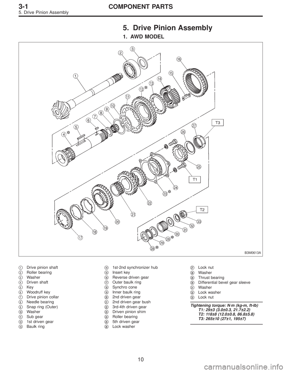
5. Drive Pinion Assembly
1. AWD MODEL
B3M0613A
�1Drive pinion shaft
�
2Roller bearing
�
3Washer
�
4Driven shaft
�
5Key
�
6Woodruff key
�
7Drive pinion collar
�
8Needle bearing
�
9Snap ring (Outer)
�
10Washer
�
11Sub gear
�
121st driven gear
�
13Baulk ring�
141st-2nd synchronizer hub
�
15Insert key
�
16Reverse driven gear
�
17Outer baulk ring
�
18Synchro cone
�
19Inner baulk ring
�
202nd driven gear
�
212nd driven gear bush
�
223rd-4th driven gear
�
23Driven pinion shim
�
24Roller bearing
�
255th driven gear
�
26Lock washer�
27Lock nut
�
28Washer
�
29Thrust bearing
�
30Differential bevel gear sleeve
�
31Washer
�
32Lock washer
�
33Lock nut
Tightening torque: N⋅m (kg-m, ft-lb)
T1: 29±3 (3.0±0.3, 21.7±2.2)
T2: 118±8 (12.0±0.8, 86.8±5.8)
T3: 265±10 (27±1, 195±7)
10
3-1COMPONENT PARTS
5. Drive Pinion Assembly
Page 643 of 3342
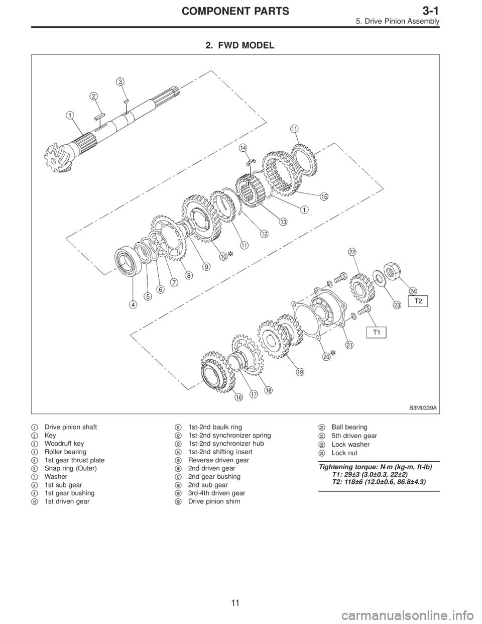
2. FWD MODEL
B3M0339A
�1Drive pinion shaft
�
2Key
�
3Woodruff key
�
4Roller bearing
�
51st gear thrust plate
�
6Snap ring (Outer)
�
7Washer
�
81st sub gear
�
91st gear bushing
�
101st driven gear�
111st-2nd baulk ring
�
121st-2nd synchronizer spring
�
131st-2nd synchronizer hub
�
141st-2nd shifting insert
�
15Reverse driven gear
�
162nd driven gear
�
172nd gear bushing
�
182nd sub gear
�
193rd-4th driven gear
�
20Drive pinion shim�
21Ball bearing
�
225th driven gear
�
23Lock washer
�
24Lock nut
Tightening torque: N⋅m (kg-m, ft-lb)
T1: 29±3 (3.0±0.3, 22±2)
T2: 118±6 (12.0±0.6, 86.8±4.3)
11
3-1COMPONENT PARTS
5. Drive Pinion Assembly
Page 683 of 3342
 Remove roller bearing and washer (33 x 50 x 5) using
ST and press.
ST 498077000 REMOVER
CAUTION:
Do not reuse roller bearing.
G3M0608
2. DRIVEN GEAR ASSEMBLY (2200 cc MODEL)
CAUTION:
Attach")
G3M0607
3) Remove roller bearing and washer (33 x 50 x 5) using
ST and press.
ST 498077000 REMOVER
CAUTION:
Do not reuse roller bearing.
G3M0608
2. DRIVEN GEAR ASSEMBLY (2200 cc MODEL)
CAUTION:
Attach a cloth to the end of driven shaft (on the fric-
tional side of thrust needle bearing) during disassem-
bly or reassembly to prevent damage.
1) Straighten lock nut at staked portion. Remove the lock
nut using ST1 and ST2.
ST1 499987300 SOCKET WRENCH (50)
ST2 899884100 HOLDER
G3M0609
2) Remove 5th driven gear using ST.
ST 499857000 5TH DRIVEN GEAR REMOVER
G3M0610
3) Remove woodruff key.
4) Remove roller bearing (42 x 74 x 40), 3rd and 4th driven
gear using ST1 and ST2.
ST1 499757002 SNAP RING PRESS
ST2 899714110 REMOVER
G3M0611
5) Remove the key.
6) Remove 2nd driven gear assembly.
7) Remove 1st driven gear, 2nd gear bushing, gear and
hub using ST1 and ST2.
Replace gear and hub if necessary. Do not attempt to dis-
assemble if at all possible because they must engage at a
specified point. If they have to be disassembled, mark the
engaging point beforehand.
ST1 499757002 SNAP RING PRESS
ST2 899714110 REMOVER
50
3-1SERVICE PROCEDURE
5. Drive Pinion Assembly (AWD Model)
Page 684 of 3342
8) Remove sub gears for 1st and 2nd driven gear.
G3M0608
3. DRIVEN GEAR ASSEMBLY (2500 cc MODEL)
CAUTION:
Attach a cloth to the end of driven shaft (on the fric-
tional side of thrust needle bearing) during disassem-
bly or reassembly to prevent damage.
1) Straighten lock nut at staked portion. Remove the lock
nut using ST1 and ST2.
ST1 499987300 SOCKET WRENCH (50)
ST2 899884100 HOLDER
G3M0609
2) Remove 5th driven gear using ST.
ST 499857000 5TH DRIVEN GEAR REMOVER
G3M0610
3) Remove woodruff key.
4) Remove roller bearing (42 x 74 x 40), 3rd-4th driven
gear using ST1 and ST2.
ST1 499757002 SNAP RING PRESS
ST2 899714110 REMOVER
B3M0426A
5) Remove the key.
6) Remove 2nd driven gear�
1, inner baulk ring�2, synchro
cone�
3and outer baulk ring�4.
51
3-1SERVICE PROCEDURE
5. Drive Pinion Assembly (AWD Model)
Page 685 of 3342
G3M0611
7) Remove 1st driven gear, 2nd gear bushing, gear and
hub using ST1 and ST2.
NOTE:
Replace gear and hub if necessary. Do not attempt to dis-
assemble if at all possible because they must engage at a
specified point. If they have to be disassembled, mark the
engaging point beforehand.
ST1 499757002 SNAP RING PRESS
ST2 899714110 REMOVER
8) Remove sub gear for 1st driven gear.
B3M0077A
B: ASSEMBLY
1. GEAR AND HUB ASSEMBLY (2200 cc MODEL)
NOTE:
Position open ends of springs 120°apart.
�
A: 1st gear side
�
B: 2nd gear side
�
C: Flush surface
�
D: Stepped surface
B3M0431A
2. GEAR AND HUB ASSEMBLY (2500 cc MODEL)
Assemble gear and hub assembly.
NOTE:
�Use new gear and hub assembly, if gear or hub have
been replaced.
�Be sure the insert keys are correctly located in the insert
key grooves�
1inside the reverse driven gear�2.
B3M0077A
�A: 1st gear side
�
B: 2nd gear side
�
C: Flush surface
�
D: Stepped surface
52
3-1SERVICE PROCEDURE
5. Drive Pinion Assembly (AWD Model)
 Check sprocket teeth for abnormal wear and scratches.
2) Make sure there is no free play between sprocket and
key.
3) Check crankshaft sprocket notch for sensor for damage
and contamina")
 Installation of valve spring and valve
(1) Coat stem of each valve with engine oil and insert
valve into valve guide.
CAUTION:
When inserting valve into valve guide, u")
 Remove sub gears for 1st and 2nd driven gear.
G3M0608
3. DRIVEN GEAR ASSEMBLY (2500 cc MODEL)
CAUTION:
Attach a cloth to the end of driven shaft (on the fric-
tional side of thrust needle bearing)")
 Remove 1st driven gear, 2nd gear bushing, gear and
hub using ST1 and ST2.
NOTE:
Replace gear and hub if necessary. Do not attempt to dis-
assemble if at all possible because they must engag")