Page 1803 of 3342
B6M0377
4. KEY CYLINDER LOCK/UNLOCK SWITCH AND
TAMPER SWITCH
Door Switch
1) Disconnect connector of door key cylinder switch.
2) Move switch by turning the key cylinder with ignition key
and/or remove switch from key cylinder to check continuity
between terminals as indicated in table below:
Terminal
Switch position1234
Normal
LOCK��
UNLOCK��
Switch is removed from
key cylinder.��
B6M0378A
Trunk Lid Switch (SEDAN)
1) Disconnect connector of trunk lid key cylinder switch.
2) Move switch by turning the key cylinder with ignition key
and/or remove switch from key cylinder to check continuity
between terminals as indicated in table below:
Terminal
Switch position123
Normal
UNLOCK��
Switch is removed from
key cylinder.��
58
6-2SERVICE PROCEDURE
22. Security System
Page 1804 of 3342
B6M0379
Rear Gate Switch (WAGON)
1) Disconnect connector of rear gate key cylinder switch.
2) Move switch by turning the key cylinder with ignition key
and check continuity between terminals as indicated in
table below:
Terminal
Switch position124
Normal
LOCK��
UNLOCK��
B6M0133A
B6M0381A
5. DOOR LOCK/UNLOCK SWITCH
NOTE:
The door lock/unlock switch is united with the power door
lock actuator.
1) Disconnect connector of door lock/unlock switch.
2) Set switch to each position and check continuity
between terminals as indicated in table below:
Driver’s Door
Terminal
Switch position12
UNLOCK��
LOCK
Passenger’s Door
Terminal
Switch position1234
UNLOCK��
LOCK
Rear Gate (WAGON)
Terminal
Switch position1234
UNLOCK��
LOCK
59
6-2SERVICE PROCEDURE
22. Security System
Page 1806 of 3342
 Fully open all the door windows.
2) Turn the ignition switch to OFF and remove ignition key
from ignition switch.
3) Get out of the vehicle and lock th")
C: FUNCTION TEST
1. SECURITY SYSTEM OPERATION
1) Fully open all the door windows.
2) Turn the ignition switch to OFF and remove ignition key
from ignition switch.
3) Get out of the vehicle and lock the driver’s door using a
ignition key.
4) Check that the security indicator light illuminates.
5) When the security indicator light illuminates, wait for 30
seconds.
After 30 seconds, check that the light starts repeating 0.2
sec. ON and 2.4 sec. OFF sequence.
6) Unlock the driver’s door using the inside lock knob and
open the door.
Ensure that:
(1) the horn sounds and headlights flash intermittently
at 0.2 sec. ON and 0.6 sec. OFF. intervals, and
(2) the engine will not start even if the ignition switch
is turned to START.
7) Unlock the driver’s door one time using the ignition key.
Ensure the horn and headlights turn off.
8) Close and lock the driver’s door without using a ignition
key. (Set the inside lock knob to LOCK and then close the
door while lifting the outer handle).
Check that the security indicator light illuminates continu-
ously.
9) Within 30 seconds after the above step 8), unlock the
rear LH door using the inside lock knob and open the door.
Check that the security indicator light flashes at 0.5 sec.
intervals.
10) Close the rear LH door and lock the door using the
inside lock knob.
Check that the security indicator light illuminates continu-
ously.
11) Perform the above steps 9) and 10) on the rear RH
door and front RH door.
12) Within 30 seconds after above step 11) has been
finished, pull the engine hood opener lever and open the
engine hood.
Check that the security indicator light flashes at 0.5 sec.
intervals.
13) Close the engine hood completely.
Check that the security indicator light illuminates continu-
ously.
61
6-2SERVICE PROCEDURE
22. Security System
Page 1807 of 3342
 Within 30 seconds after the above step 13), pull the
trunk lid opener lever and open the trunk lid (SEDAN); or
unlock the rear gate by operating the driver’s door inside
lock knob and open the r")
14) Within 30 seconds after the above step 13), pull the
trunk lid opener lever and open the trunk lid (SEDAN); or
unlock the rear gate by operating the driver’s door inside
lock knob and open the rear gate (WAGON).
Check that the security indicator light flashes at 0.5 sec.
intervals.
15) Close the trunk lid completely (SEDAN); or close the
rear gate and lock by locking the driver’s door using a igni-
tion key (WAGON).
Check that the security indicator light illuminates continu-
ously.
16) When the security indicator light illuminates
continuously, wait for 30 seconds.
After 30 seconds, check that the light starts repeating 0.2
sec. ON and 2.4 sec. OFF sequence.
17) Unlock the trunk lid (SEDAN) or rear gate (WAGON)
using a ignition key and open.
Check that the horn and headlights do not operate.
18) Close the trunk lid (SEDAN) or rear gate (WAGON).
19) Unlock and then lock the driver’s door using a ignition
key and wait for 30 seconds.
After 30 seconds, check that the light starts repeating 0.2
sec. ON and 2.4 sec. OFF sequence.
20) Only WAGON model; unlock and then lock the rear
gate using a ignition key and wait for 30 seconds.
After 30 seconds, check that the light starts repeating 0.2
sec. ON and 2.4 sec. OFF sequence.
21) Unlock the front RH door using a ignition key and open
the door.
Check that the horn and headlights do not operate.
After finishing the above checks, ensure that security sys-
tem’s function is correct.
62
6-2SERVICE PROCEDURE
22. Security System
Page 1814 of 3342
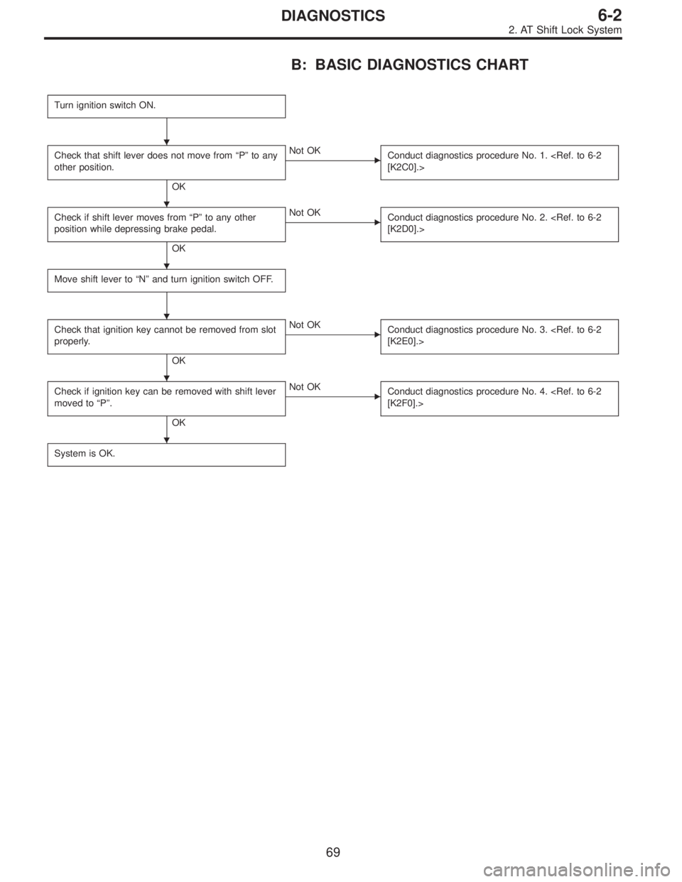
B: BASIC DIAGNOSTICS CHART
Turn ignition switch ON.
Check that shift lever does not move from“P”to any
other position.
OK
�Not OK
Conduct diagnostics procedure No. 1.
[K2C0].>
Check if shift lever moves from“P”to any other
position while depressing brake pedal.
OK
�Not OK
Conduct diagnostics procedure No. 2.
[K2D0].>
Move shift lever to“N”and turn ignition switch OFF.
Check that ignition key cannot be removed from slot
properly.
OK
�Not OK
Conduct diagnostics procedure No. 3.
[K2E0].>
Check if ignition key can be removed with shift lever
moved to“P”.
OK
�Not OK
Conduct diagnostics procedure No. 4.
[K2F0].>
System is OK.
�
�
�
�
�
�
69
6-2DIAGNOSTICS
2. AT Shift Lock System
Page 1817 of 3342

Check if shift lock operates properly.
OK
�Not OK
Check diagnostics procedure“No. 1”or“No. 2”.
Check if voltage between shift l")
E: DIAGNOSTICS PROCEDURE No. 3 (KEY
INTERLOCK DOES NOT OPERATE.)
Check if shift lock operates properly.
OK
�Not OK
Check diagnostics procedure“No. 1”or“No. 2”.
Check if voltage between shift lock control module
terminal No. 8 and body is at least 10 V when
ignition key is inserted in its slot.
OK
�Not OK
Faulty key switch.
Repair or replace wiring harness or faulty connector
between fuse box and shift lock control module.
Check if voltage between shift lock control module
terminal No. 7 and body is at least 10 V when
ignition switch is set to ACC.
OK
�Not OK
Repair or replace wiring harness or faulty connector
between ignition switch and shift lock control
module.
Disconnect connector from shift lock control module.
Check if resistance between terminal No. 9 and
terminal No. 11 of shift lock control module
connector is less than 8Ω.
OK
�Not OK
Key lock solenoid circuit open. Repair or replace
wiring harness or faulty connector between key lock
solenoid and shift lock control module.
Voltage is at least 4 V. (*)
OK
�Not OK
Key lock solenoid is shorted.
Repair or replace wiring harness or faulty connector
between key lock solenoid and shift lock control
module.
* After repairs, recheck for proper operation.
If still faulty, replace shift lock control module.
Check if resistance between terminal No. 11 of shift
lock control module connector and body is at least 1
MΩ.
OK
�Not OK
Replace shift lock control module.
*: When conducting operational checks of the key lock solenoid, do not apply 12 V to solenoid for more than one second, since
this may break solenoid circuit.
�
�
�
�
�
�
72
6-2DIAGNOSTICS
2. AT Shift Lock System
Page 1818 of 3342

Check if shift lock operates properly.
OK
�Not OK
Check diagnostics procedure“No. 1”or“No. 2”.
Check if voltage between shift l")
F: DIAGNOSTICS PROCEDURE No. 4 (KEY
INTERLOCK DOES NOT RELEASE.)
Check if shift lock operates properly.
OK
�Not OK
Check diagnostics procedure“No. 1”or“No. 2”.
Check if voltage between shift lock control module
terminal No. 8 and body is at least 10 V when
ignition key is inserted in its slot.
OK
�Not OK
Faulty key switch. Repair or replace wiring harness
or faulty connector between fuse box and shift lock
control module.
Check if voltage between shift lock control module
terminal No. 7 and body is at least 10 V when
ignition switch is set to ACC.
OK
�Not OK
Repair or replace wiring harness or faulty connector
between ignition switch and shift lock control
module.
Disconnect connector from shift lock control module.
Check if resistance between terminal No. 9 and
terminal No. 11 of shift lock control module
connector is less than 8Ω. (*)
OK
�Not OK
Key lock solenoid circuit open.
Repair or replace wiring harness or faulty connector
between key lock solenoid and shift lock control
module.
Voltage is at least 4 V.
OK
�Not OK
Key lock solenoid is shorted.
Repair or replace wiring harness or faulty connector
between key lock solenoid and shift lock control
module.
* After repairs, recheck for proper operation.
If still faulty, replace shift lock control module.
Check if resistance between terminal No. 9 of shift
lock control module connector and body is at least 1
MΩ.
OK
�Not OK
Repair or replace wiring harness or faulty connector
between key lock solenoid and shift lock control
module.
* After repairs, recheck for proper operation.
If still faulty, replace shift lock control module.
Replace shift lock control module.
*: When conducting operational checks of the key lock solenoid, do not apply 12 V to solenoid for more than one second, since
this may break solenoid circuit.
�
�
�
�
�
�
73
6-2DIAGNOSTICS
2. AT Shift Lock System
Page 1832 of 3342
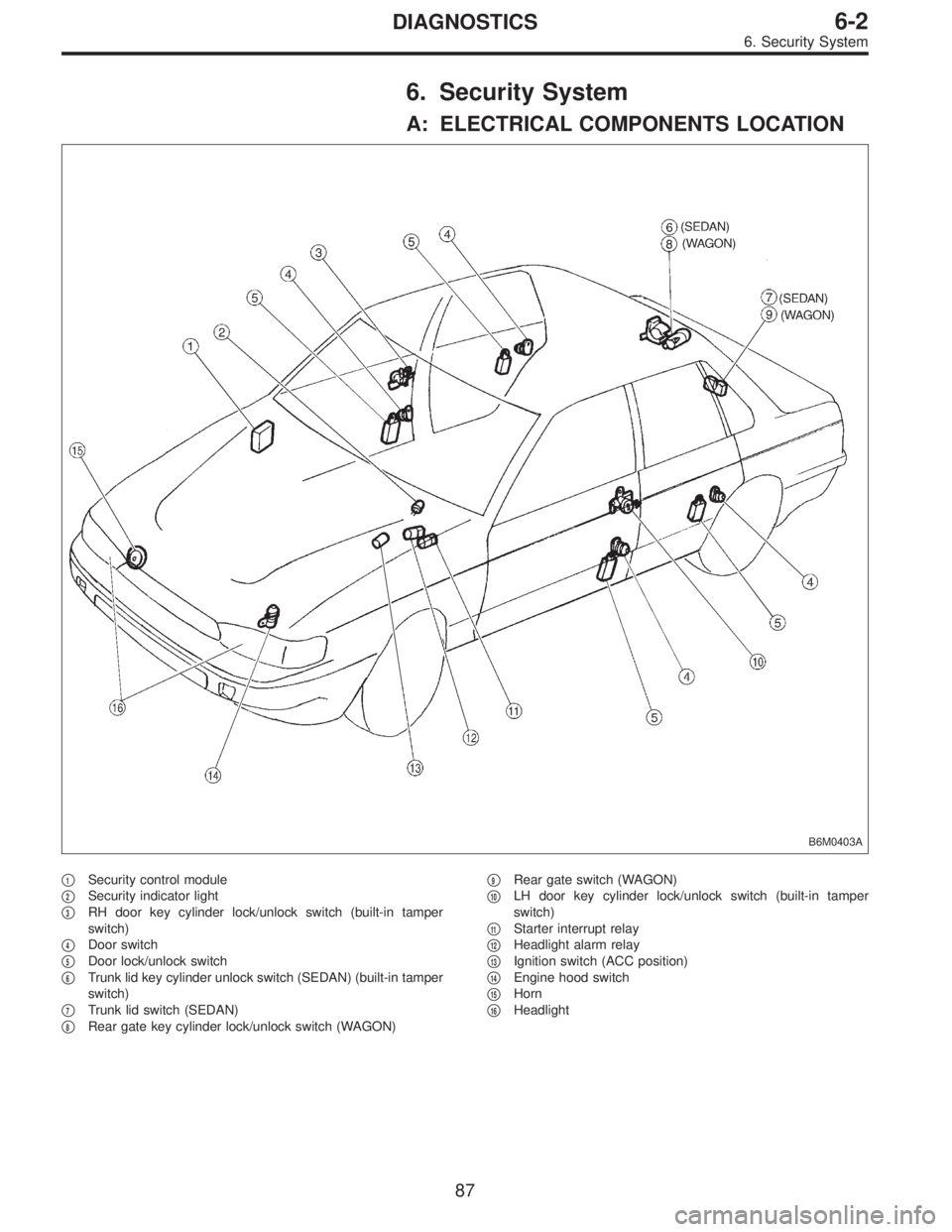
6. Security System
A: ELECTRICAL COMPONENTS LOCATION
B6M0403A
�1Security control module
�
2Security indicator light
�
3RH door key cylinder lock/unlock switch (built-in tamper
switch)
�
4Door switch
�
5Door lock/unlock switch
�
6Trunk lid key cylinder unlock switch (SEDAN) (built-in tamper
switch)
�
7Trunk lid switch (SEDAN)
�
8Rear gate key cylinder lock/unlock switch (WAGON)�
9Rear gate switch (WAGON)
�
10LH door key cylinder lock/unlock switch (built-in tamper
switch)
�
11Starter interrupt relay
�
12Headlight alarm relay
�
13Ignition switch (ACC position)
�
14Engine hood switch
�
15Horn
�
16Headlight
87
6-2DIAGNOSTICS
6. Security System
 Disconnect connector of door key cylinder switch.
2) Move switch by turning the key cylinder with ignition key
and/or remove")

1) Disconnect connector of rear gate key cylinder switch.
2) Move switch by turning the key cylinder with ignition key
and check continuity between terminals as indica")