Page 1909 of 3342
51. READ DATA FUNCTION KEY LIST FOR AT
Function mode Contents Abbr. Unit
F00 Mode display E-4AT—
F01 Battery voltage VB V
F02 Vehicle speed sensor 1 signal VSP1 m/h
F03 Vehicle speed sensor 1 signal VSP1 km/h
F04 Vehicle speed sensor 2 signal VSP2 m/h
F05 Vehicle speed sensor 2 signal VSP2 km/h
F06 Engine speed EREV rpm
F07 ATF temperature sensor signal ATFT deg F
F08 ATF temperature sensor signal ATFT deg C
F09 Throttle position sensor signal THV V
F10 Gear position GEAR—
F11 Line pressure duty ratio PLDTY %
F12 Lock-up duty ratio LUDTY %
F13 AWD duty ratio 4WDTY %
F14 Throttle position sensor power supply voltage THVCC V
F15 Mass air flow sensor signal AFM V
58
2-7ON-BOARD DIAGNOSTICS II SYSTEM
3. Diagnosis System
Page 1915 of 3342
H2M1149
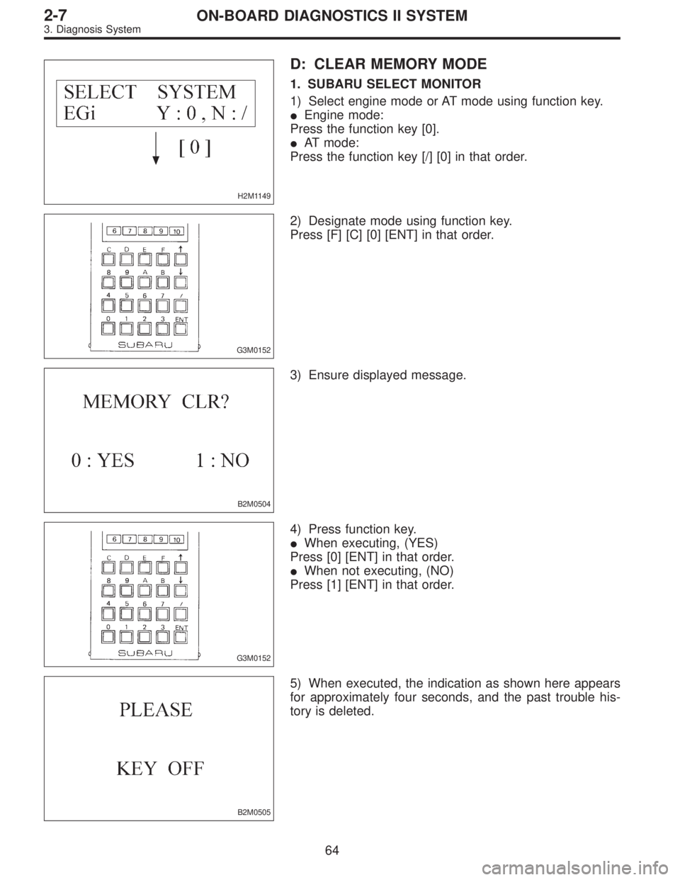
D: CLEAR MEMORY MODE
1. SUBARU SELECT MONITOR
1) Select engine mode or AT mode using function key.
�Engine mode:
Press the function key [0].
�AT mode:
Press the function key [/] [0] in that order.
G3M0152
2) Designate mode using function key.
Press [F] [C] [0] [ENT] in that order.
B2M0504
3) Ensure displayed message.
G3M0152
4) Press function key.
�When executing, (YES)
Press [0] [ENT] in that order.
�When not executing, (NO)
Press [1] [ENT] in that order.
B2M0505
5) When executed, the indication as shown here appears
for approximately four seconds, and the past trouble his-
tory is deleted.
64
2-7ON-BOARD DIAGNOSTICS II SYSTEM
3. Diagnosis System
Page 1921 of 3342
 Start the engine.
NOTE:
�Ensure the selector lever is placed in the“P”position
before starting. (AT vehicles)
�Depress clutch pedal when starting the engine. (MT
vehicles)
4) Using the selector")
3) Start the engine.
NOTE:
�Ensure the selector lever is placed in the“P”position
before starting. (AT vehicles)
�Depress clutch pedal when starting the engine. (MT
vehicles)
4) Using the selector lever or shift lever, turn the“P”posi-
tion switch and the“N”position switch to ON.
5) Depress the brake pedal to turn the brake switch ON.
(AT vehicles)
6) Keep engine speed in the 2,500—3,000 rpm range for
40 seconds.
NOTE:
On models without tachometer, use the Subaru select
monitor or tachometer (Secondary pickup type).
7) Place the selector lever or shift lever in the“D”position
(AT vehicles) or“1st”gear (MT vehicles) and drive the
vehicle at 5 to 10 km/h (3 to 6 MPH).
NOTE:
�On AWD vehicles, release the parking brake.
�The speed difference between front and rear wheels
may light either the ABS or the ABS/TCS warning light, but
this indicates no malfunctions. When engine control diag-
nosis is finished, perform the ABS or the ABS/TCS memory
clearance procedure of self-diagnosis system.
4-4b [T6D2] or [T9K0], or 4-4c [T6D2] or [T9J0], or 4-4d
[T6D2] or [T9J0].>
8) Using the OBD-II general scan tool, check for diagnos-
tic trouble code(s) and record the result(s).
NOTE:
�For detailed operation procedures, refer to the OBD-II
General Scan Tool Instruction Manual.
�For details concerning diagnostic trouble codes, refer to
the DIAGNOSTIC TROUBLE CODE (DTC) LIST.
2-7 [T10A0], [T11A0].>
H2M1149
4. READ DIAGNOSTIC TROUBLE CODE (DTC)
SHOWN ON DISPLAY. (MODE FB0
MODE>)
Using Subaru select monitor, check for diagnostic trouble
code(s) and record the result(s).
1) Select engine mode using function key.
Press the function key [0].
70
2-7ON-BOARD DIAGNOSTICS II SYSTEM
3. Diagnosis System
Page 1922 of 3342
G3M0152
2) Designate mode using function key.
Press [F] [B] [0] [ENT] in that order.
OBD0086
3) Ensure diagnostic trouble code(s) is shown.
(1) When there is only one diagnostic trouble code.
OBD0087
(2) When there are multiple diagnostic trouble codes.
NOTE:
For details concerning diagnostic trouble code(s), refer to
the DIAGNOSTIC TROUBLE CODE (DTC) LIST.
2-7 [T10A0], [T11A0].>
OBD0057A
F: COMPULSORY VALVE OPERATION
CHECK MODE
1. SUBARU SELECT MONITOR
1) Prepare Subaru select monitor and cartridge.
ST1 498307500 SELECT MONITOR KIT
ST2 498346300 CARTRIDGE
G3M0151
2) Turn ignition switch and Subaru select monitor switch to
OFF.
71
2-7ON-BOARD DIAGNOSTICS II SYSTEM
3. Diagnosis System
Page 1924 of 3342
OBD0669A
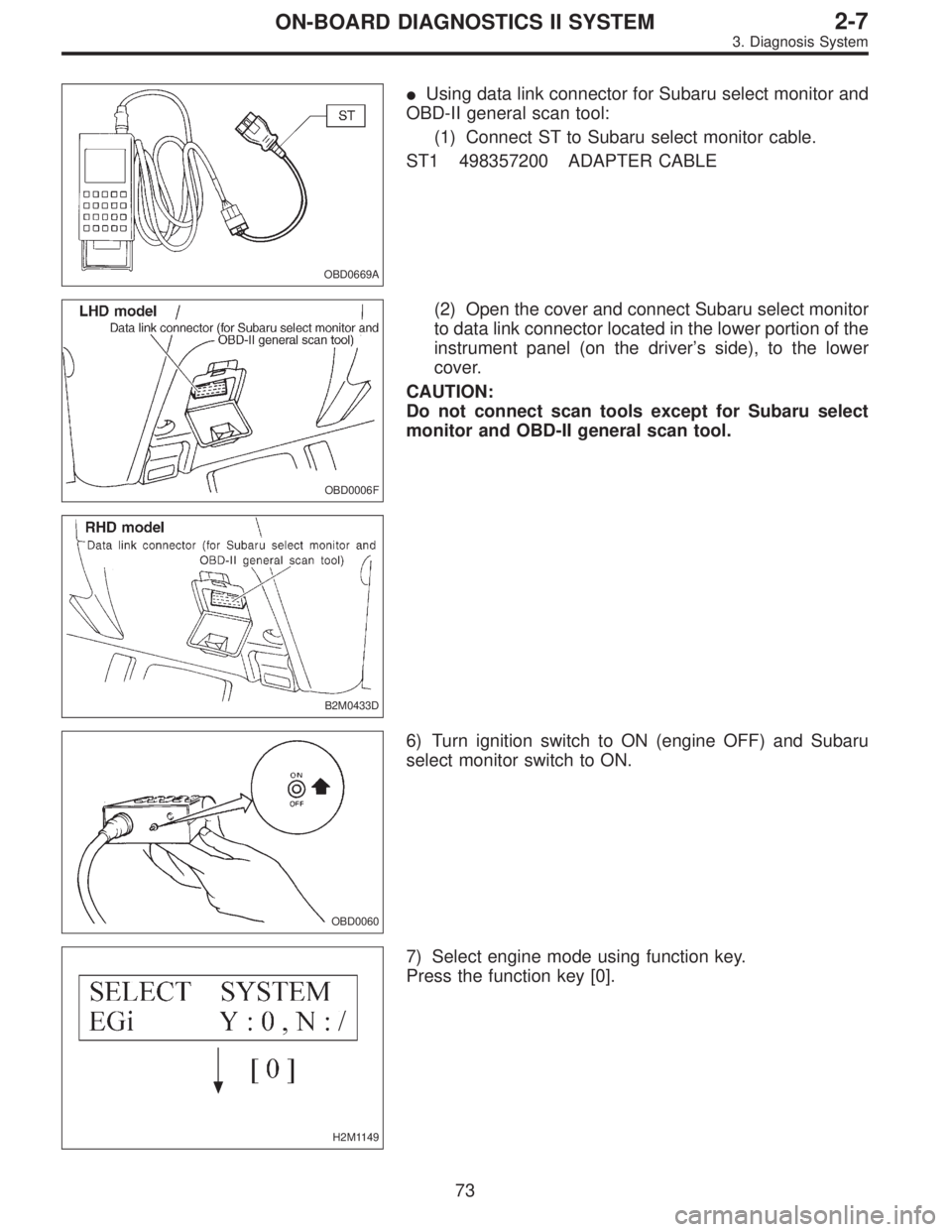
�Using data link connector for Subaru select monitor and
OBD-II general scan tool:
(1) Connect ST to Subaru select monitor cable.
ST1 498357200 ADAPTER CABLE
OBD0006F
B2M0433D
(2) Open the cover and connect Subaru select monitor
to data link connector located in the lower portion of the
instrument panel (on the driver’s side), to the lower
cover.
CAUTION:
Do not connect scan tools except for Subaru select
monitor and OBD-II general scan tool.
OBD0060
6) Turn ignition switch to ON (engine OFF) and Subaru
select monitor switch to ON.
H2M1149
7) Select engine mode using function key.
Press the function key [0].
73
2-7ON-BOARD DIAGNOSTICS II SYSTEM
3. Diagnosis System
Page 1925 of 3342
G3M0152
8) Designate mode using function key.
(Example: Press [F] [D] [0] [5] [ENT] in that order.)
B2M0650
9) Ensure displayed message.
B2M0651
10) Press the function key.
(1) When executing, press the function key [0].
B2M0652
NOTE:
When in compulsory valve operation check mode the moni-
tor indicates the execution of valve check on display.
B2M0653
(2) When not executing or stopping the compulsory
valve check mode, press the function key [1].
74
2-7ON-BOARD DIAGNOSTICS II SYSTEM
3. Diagnosis System
Page 1986 of 3342
 Turn ignition switch to OFF.
2) Connect Subaru Select Monitor or the OBD-II general
scan tool to data link")
OBD0145A
10C1CONNECT SUBARU SELECT MONITOR
OR THE OBD-II GENERAL SCAN TOOL,
AND READ DATA.
1) Turn ignition switch to OFF.
2) Connect Subaru Select Monitor or the OBD-II general
scan tool to data link connector.
3) Turn ignition switch to ON and Subaru Select Monitor or
the OBD-II general scan tool switch to ON.
4) Start engine.
B2M0481
5) Read data on Subaru Select Monitor or OBD-II general
scan tool.
�Subaru Select Monitor
Designate mode using function key.
Function mode: F06
�F06: Mass air flow and voltage input from mass air flow
sensor are shown on display at the same time.
: Is the value equal to or more than 1.3 g/sec
or 0.3 V and equal to or less than 250 g/sec
or 5.0 V in function mode F06?
Probable cause: Poor connect of connectors, circuit and
grounding line.
: Even if MIL lights up, the circuit has returned to a
normal condition at this time. A temporary poor
contact of the connector or harness may be the
cause. Repair harness or connector in the mass
air flow sensor.
NOTE:
In this case, repair the following:
�Open or ground short circuit in harness between mass
air flow sensor and ECM connector
�Poor contact in mass air flow sensor or ECM connector
: Go to step10C2.
135
2-7ON-BOARD DIAGNOSTICS II SYSTEM
10. Diagnostic Chart with Trouble Code for LHD Vehicles
Page 1990 of 3342
OBD0145A
10D1CONNECT SUBARU SELECT MONITOR
OR THE OBD-II GENERAL SCAN TOOL,
AND READ DATA.
1) Turn ignition switch to OFF.
2) Connect Subaru Select Monitor or the OBD-II general
scan tool to data link connector.
3) Turn ignition switch to ON and Subaru Select Monitor or
the OBD-II general scan tool switch to ON.
4) Start engine.
B2M0481
5) Read data on Subaru Select Monitor or OBD-II general
scan tool.
�Subaru Select Monitor
Designate mode using function key.
Function mode: F06
�F06: Mass air flow and voltage input from mass air flow
sensor are shown on display at the same time.
: Is the value equal to or more than 1.3 g/sec
or 0.3 V and equal to or less than 250 g/sec
or 5.0 V in function mode F06?
Probable cause: Poor connect of connectors, circuit and
grounding line.
: Even if MIL lights up, the circuit has returned to a
normal condition at this time.
: Go to step10D2.
139
2-7ON-BOARD DIAGNOSTICS II SYSTEM
10. Diagnostic Chart with Trouble Code for LHD Vehicles

![SUBARU LEGACY 1997 Service Repair Manual G3M0152
2) Designate mode using function key.
Press [F] [B] [0] [ENT] in that order.
OBD0086
3) Ensure diagnostic trouble code(s) is shown.
(1) When there is only one diagnostic trouble code.
OBD0087](/manual-img/17/57434/w960_57434-1921.png "SUBARU LEGACY 1997 Service Repair Manual G3M0152
2) Designate mode using function key.
Press [F] [B] [0] [ENT] in that order.
OBD0086
3) Ensure diagnostic trouble code(s) is shown.
(1) When there is only one diagnostic trouble code.
OBD0087")
![SUBARU LEGACY 1997 Service Repair Manual G3M0152
8) Designate mode using function key.
<Ref. to 2-7 [T3C6].>
(Example: Press [F] [D] [0] [5] [ENT] in that order.)
B2M0650
9) Ensure displayed message.
B2M0651
10) Press the function key.
(1) W](/manual-img/17/57434/w960_57434-1924.png "SUBARU LEGACY 1997 Service Repair Manual G3M0152
8) Designate mode using function key.
<Ref. to 2-7 [T3C6].>
(Example: Press [F] [D] [0] [5] [ENT] in that order.)
B2M0650
9) Ensure displayed message.
B2M0651
10) Press the function key.
(1) W")
 Turn ignition switch to OFF.
2) Connect Subaru Select Monitor or the OBD-II general
scan tool to data link")