Page 1465 of 3342

3. Tools and Equipment
The following section provides information about the tools
and equipment that will be necessary to properly service
the A/C system.
Since equipment may vary slightly depending on the
manufacturer, it is important to always read and follow the
manufacturer’s instructions.
CAUTION:
When working on vehicles with the HFC-134a system,
only use HFC-134a specified tools and parts. Do not
mix with CFC-12 tools and parts. If HFC-134a and
CFC-12 refrigerant or compressor oil is mixed, poor
lubrication will result and the compressor itself may be
destroyed.
In order to help prevent mixing HFC-134a and CFC-12
parts and liquid, the tool and screw type and the type
of service valves used are different. The gas leak
detectors for the HFC-134a and CFC-12 systems must
also not be interchanged.
HFC-134a CFC-12
Tool & screw type Millimeter size Inch size
Valve type Quick joint type Screw-in type
Tools and Equipment Description
�WRENCH
VariousWRENCHESwill be required to service any A/C
system. A 7 to 40 N⋅m (0.7 to 4.1 kg-m, 5 to 30 ft-lb) torque
wrench with various crowfoot wrenches will be needed. Open
end or flare nut wrenches will be needed for back-up on the
tube and hose fittings.
G4M0571
�APPLICATOR BOTTLE
A smallAPPLICATOR BOTTLEis recommended to apply
refrigerant oil to the various parts. They can be obtained at a
hardware or drug store.
G4M0572
12
4-7SERVICE PROCEDURE
3. Tools and Equipment
Page 1477 of 3342
 Begin at the connection of the high-pressure tube to the")
G4M0612
4. LEAK TEST — HIGH-PRESSURE SIDE
Operate the A/C system for approx. 10 minutes, then turn
the engine off and begin the leak test.
1) Begin at the connection of the high-pressure tube to the
evaporator, and work your way along the high- pressure
side of the system to the compressor. There are three
places to check on each tube connection.
2) Check the area.
(1) Check the area where the fitting joins the tube.
G4M0613
(2) Check the area where the two parts of the fitting
join each other.
G4M0614
(3) Check the area where the nut joins the tube.
3) Check the area of the sight glass and pressure switch
(dual switch), and also check the seams of the receiver
drier.
4) Check the connections of the tubes to the condenser,
and also check any welded joints on the condenser.
CAUTION:
An oily area on the fins of the condenser may indicate
a leak.
5) Check the area where the hoses attach to the compres-
sor.
6) Check around the machined portions of the compressor
(where the compressor sections join each other).
7) If equipped, check the thermal limiter on the compres-
sor housing.
8) Check the compressor shaft seal by probing near the
center of the compressor clutch pulley.
NOTE:
Some shaft seals have a very slight amount of normal
leakage [approximately 28 g (1.0 oz) per year].
24
4-7SERVICE PROCEDURE
8. Leak Testing
Page 1484 of 3342

11. Compressor
Compressor is a swash plate type. When trouble occurs,
replace compressor as a single unit.
B4M0090
A: COMPRESSOR CLUTCH INSPECTION
Compressor clutch trouble is often caused by clutch slip-
page and noise. Check and take corrective measures, as
required.
1) Remove belt cover.
2) Check that clearance between drive plate and pulley
over the entire perimeter is within specifications.
Clearance:
0.3 — 0.6 mm (0.012 — 0.024 in)
B4M0091
3) Check that voltage applied to magnetic coil is at least
10.5 volts.
4) When noise is noted, check that it originates in either
compressor or pulley bearing.
B4M0760A
B: REMOVAL
1) Disconnect ground cable from battery.
2) Discharge refrigerant using refrigerant recovery system.
(1) Fully close low-pressure valve of manifold gauge.
(2) Connect low-pressure charging hose of manifold
gauge to low-pressure service valve.
(3) Open low-pressure manifold gauge valve slightly,
and slowly discharge refrigerant from system.
CAUTION:
Do not allow refrigerant to rush out. Otherwise, com-
pressor oil will be discharged along with refrigerant.
30
4-7SERVICE PROCEDURE
11. Compressor
Page 1499 of 3342

2. Performance Test Diagnosis
If various conditions caused to other air conditioning
system, the characteristics revealed on manifold gauge
reading are shown in the following:
As to the method of a performance test, refer to the item
of“Performance Test”.
Each shaded area on the following tables indicates a read-
ing of the normal system when the temperature of outside
air is 32.5°C (91°F).
Condition Probable cause Corrective action
INSUFFICIENT REFRIGERANT CHARGE
G4M0673
Insufficient cooling Refrigerant is small, or
leaking a little.1. Perform leak test.
2. Repair leak.
3. Charge system.
Evacuate, as
necessary, and
recharge system.
ALMOST NO REFRIGERANT
G4M0674
No cooling action Serious refrigerant leak.Stop compressor
immediately.
1. Perform leak test.
2. Discharge system.
3. Repair leak(s).
4. Replace receiver
drier if necessary.
5. Check oil level.
6. Evacuate and
recharge system.
FAULTY EXPANSION VALVE
G4M0675
Slight cooling;
Sweating or frosted
expansion valve inlet.Expansion valve
restricts refrigerant flow.
�Expansion valve is
clogged.
�Expansion valve is
inoperative.
Valve stuck closed.
Thermal bulb has lost
charge.If valve inlet reveals
sweat or frost:
1. Discharge system.
2. Remove valve and
clean it. Replace it if
necessary.
3. Evacuate system.
4. Charge system.
If valve does not oper-
ate:
1. Discharge system.
2. Replace valve.
3. Evacuate and charge
system.
42
4-7DIAGNOSTICS
2. Performance Test Diagnosis
Page 1511 of 3342
 dia.
�
1Hood hinge front attaching hole M8
�
2Strut mount attaching hole (Front center) 9.5 mm (0.374 in)
dia")
1. ENGINE COMPARTMENT AND ROOM
B5M0187A
�0Cowl panel weather attaching hole 6 mm (0.24 in) dia.
�
1Hood hinge front attaching hole M8
�
2Strut mount attaching hole (Front center) 9.5 mm (0.374 in)
dia.
�
3Front fender attaching hole (Tip) M6
�
4Rear upper surface of front side frame 12 mm (0.47 in) dia.
�
5Middle upper surface of front side frame 20 mm (0.79 in) dia.
�
6Front side frame front upper surface 14 x 16 mm (0.55 x 0.63
in) dia. oblong hole
�
7Side frame of front side frame 12 mm (0.47 in) dia.
�
8Headlight attaching hole at radiator side panel 6.2x9mm
(0.244 x 0.35 in) dia.
�
9Radiator panel side (LWR) gauge hole 23 mm (0.91 in) dia.
�
23Rear strut mount attaching hole (Side) 10 mm (0.39 in) dia.
�
24Rear strut mount attaching hole (Center) 12 mm (0.47 in) dia.
�
25Radiator panel (UPR) middle hole 6 mm (0.24 in) dia.
�
26Front fender attaching hole at radiator panel side M6
�
27Front fender attaching hole at front pillar lower portion M6
�
28Hinge middle hole at front pillar center 10 mm (0.39 in) dia.
�
29Front fender attaching hole at front pillar center portion M6
�
30Retainer attaching square hole at front pillar7x7mm(0.28
x 0.28 in)�
31Retainer attaching hole at center pillar (Front) 3.5 mm (0.138
in) dia.
�
32Retainer attaching hole at center pillar (Rear) 3.5 mm (0.138
in) dia.
�
33Lower side of rear door hinge M8
�
34Center pillar (LWR) gauge hole 27 mm (1.06 in) dia.
�
35Rear quarter outer corner patch attaching hole 5.2 mm (0.205
in) dia.
�
39Front rail center notch
�
40Front glass upper locating notch RH: 6.5 mm (0.256 in) dia.,
LH: 6.5 x 10 mm (0.256 x 0.39 in) dia. oblong hole
�
41Stud bolt lower locating notch
�
48Front center of rear floor pan 8 mm (0.31 in) dia.
�
51Front upper pillar (Inner) 7 mm (0.28 in) dia.
�
52Front seat belt adjust plate attaching hole 12 mm (0.47 in)
dia.
�
53Rear door hinge middle hole 10 mm (0.39 in) dia.
�
54Rear floor, near door 8 mm (0.31 in) dia.
�
55Trim upper attaching hole at 6 light 8 mm (0.31 in) dia.
�
56Trim lower attaching hole at 6 light 8 mm (0.31 in) dia.
�
58Rear floor, near floor strut 15 x 20 mm (0.59 x 0.79 in) dia.
oblong hole
3
5-1SERVICE DATA
2. Body Datum Points
Page 1512 of 3342
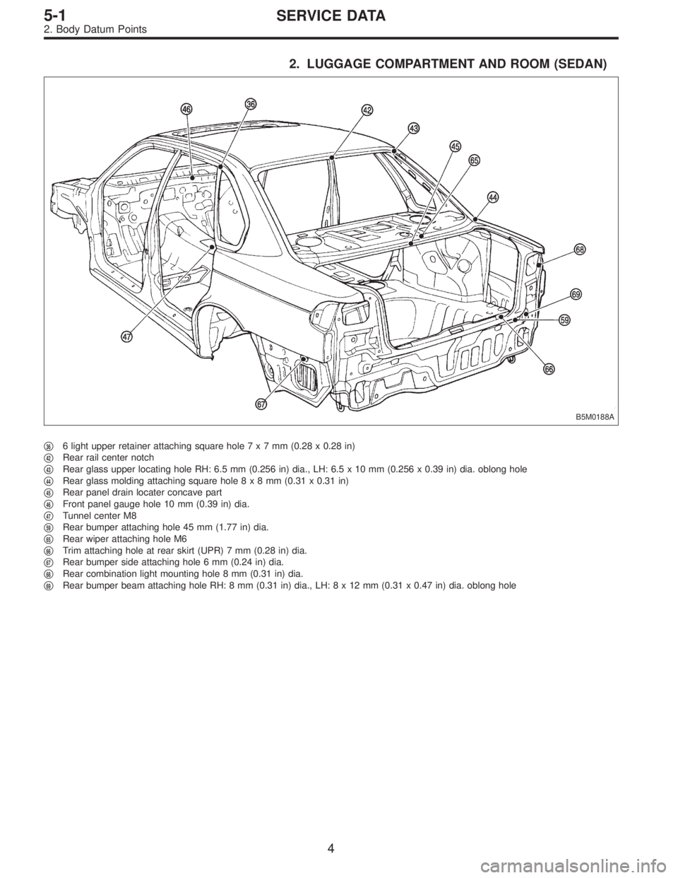
2. LUGGAGE COMPARTMENT AND ROOM (SEDAN)
B5M0188A
�366 light upper retainer attaching square hole7x7mm(0.28 x 0.28 in)
�
42Rear rail center notch
�
43Rear glass upper locating hole RH: 6.5 mm (0.256 in) dia., LH: 6.5 x 10 mm (0.256 x 0.39 in) dia. oblong hole
�
44Rear glass molding attaching square hole8x8mm(0.31 x 0.31 in)
�
45Rear panel drain locater concave part
�
46Front panel gauge hole 10 mm (0.39 in) dia.
�
47Tunnel center M8
�
59Rear bumper attaching hole 45 mm (1.77 in) dia.
�
65Rear wiper attaching hole M6
�
66Trim attaching hole at rear skirt (UPR) 7 mm (0.28 in) dia.
�
67Rear bumper side attaching hole 6 mm (0.24 in) dia.
�
68Rear combination light mounting hole 8 mm (0.31 in) dia.
�
69Rear bumper beam attaching hole RH: 8 mm (0.31 in) dia., LH:8x12mm(0.31 x 0.47 in) dia. oblong hole
4
5-1SERVICE DATA
2. Body Datum Points
Page 1513 of 3342
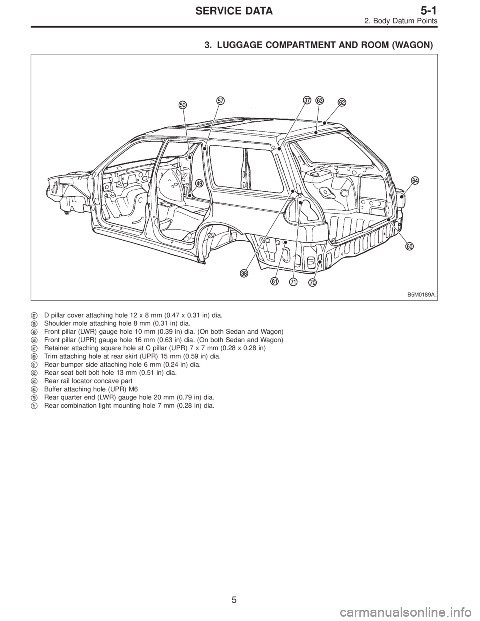
3. LUGGAGE COMPARTMENT AND ROOM (WAGON)
B5M0189A
�37D pillar cover attaching hole 12x8mm(0.47 x 0.31 in) dia.
�
38Shoulder mole attaching hole 8 mm (0.31 in) dia.
�
49Front pillar (LWR) gauge hole 10 mm (0.39 in) dia. (On both Sedan and Wagon)
�
50Front pillar (UPR) gauge hole 16 mm (0.63 in) dia. (On both Sedan and Wagon)
�
57Retainer attaching square hole at C pillar (UPR)7x7mm(0.28 x 0.28 in)
�
60Trim attaching hole at rear skirt (UPR) 15 mm (0.59 in) dia.
�
61Rear bumper side attaching hole 6 mm (0.24 in) dia.
�
62Rear seat belt bolt hole 13 mm (0.51 in) dia.
�
63Rear rail locator concave part
�
64Buffer attaching hole (UPR) M6
�
70Rear quarter end (LWR) gauge hole 20 mm (0.79 in) dia.
�
71Rear combination light mounting hole 7 mm (0.28 in) dia.
5
5-1SERVICE DATA
2. Body Datum Points
Page 1531 of 3342
4. Datum Points and Dimensions
Concerning On-Board Aiming
Adjustment
If headlight aiming is misaligned due to damaged body
panel, repair headlight mating surface using body and
headlight datum points as a guide.
NOTE:
It is recommended to conduct On-Board Aiming Adjust-
ment with headlights turned off.
If turned on during the adjustment, the duration should be
within two minutes.
B5M0364
Unit: mm (in)
22
5-1SERVICE DATA
4. Datum Points and Dimensions Concerning On-Board Aiming Adjustment