Page 1429 of 3342

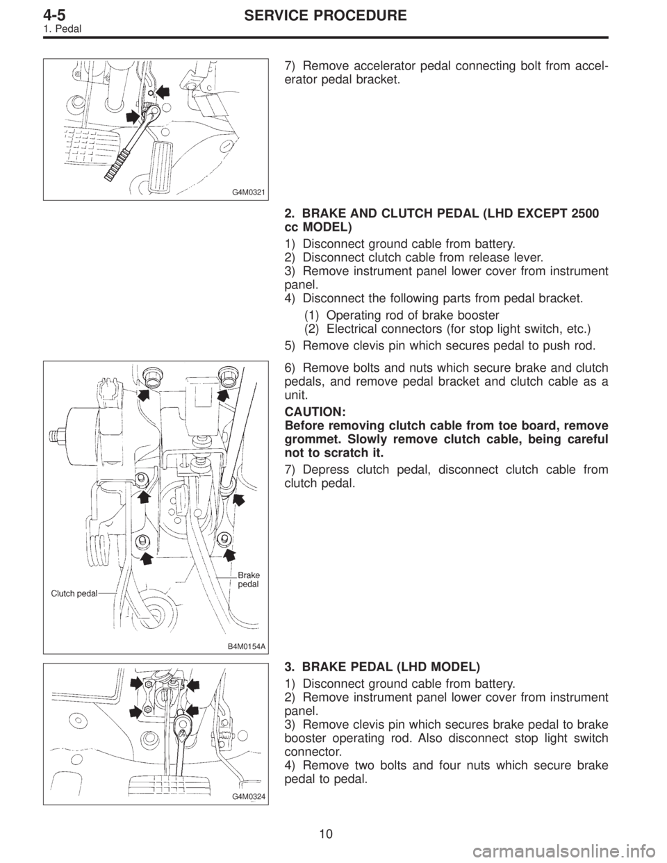
G4M0321
7) Remove accelerator pedal connecting bolt from accel-
erator pedal bracket.
2. BRAKE AND CLUTCH PEDAL (LHD EXCEPT 2500
cc MODEL)
1) Disconnect ground cable from battery.
2) Disconnect clutch cable from release lever.
3) Remove instrument panel lower cover from instrument
panel.
4) Disconnect the following parts from pedal bracket.
(1) Operating rod of brake booster
(2) Electrical connectors (for stop light switch, etc.)
5) Remove clevis pin which secures pedal to push rod.
B4M0154A
6) Remove bolts and nuts which secure brake and clutch
pedals, and remove pedal bracket and clutch cable as a
unit.
CAUTION:
Before removing clutch cable from toe board, remove
grommet. Slowly remove clutch cable, being careful
not to scratch it.
7) Depress clutch pedal, disconnect clutch cable from
clutch pedal.
G4M0324
3. BRAKE PEDAL (LHD MODEL)
1) Disconnect ground cable from battery.
2) Remove instrument panel lower cover from instrument
panel.
3) Remove clevis pin which secures brake pedal to brake
booster operating rod. Also disconnect stop light switch
connector.
4) Remove two bolts and four nuts which secure brake
pedal to pedal.
10
4-5SERVICE PROCEDURE
1. Pedal
Page 1430 of 3342
4. ACCELERATOR AND BRAKE PEDAL (RHD
MODEL)
1) Disconnect negative cable from battery.
2) Disconnect accelerator cable from throttle body.
CAUTION:
Be careful not to kink accelerator cable.
3) Remove instrument panel lower cover from instrument
panel.
4) Remove clevis pin which secures brake pedal to brake
booster operating rod. Also disconnect electrical connec-
tors (for stop light switch, etc.).
G4M0322
5) Disconnect accelerator cable from accelerator pedal
lever.
B4M0156A
6) Remove the casing cap out of the toe board by turning
it clockwise.
7) Pull out the cable from the toe board hole.
11
4-5SERVICE PROCEDURE
1. Pedal
Page 1431 of 3342
B4M0157A
8) Remove nuts and bolts which secure pedal bracket.
5. BRAKE AND CLUTCH PEDAL (2500 cc MODEL)
1) Remove steering bolts.
2) Raise vehicle on hoist and remove the two bolts which
secure steering unit to underside of body.
3) Lower vehicle to floor.
4) Remove instrument panel lower cover from instrument
panel.
5) Disconnect the following parts from pedal bracket.
�Operating rod of brake booster
�Electrical connectors (for stop light switch, etc.)
6) Remove clevis pin which secures lever to push rod.
7) Remove nut which secures clutch master cylinder.
8) Remove steering assembly.
9) Remove bolts and nuts which secure brake and clutch
pedals, and remove pedal assembly.
12
4-5SERVICE PROCEDURE
1. Pedal
Page 1432 of 3342
G4M0325
G4M0326
C: INSPECTION
1. BRAKE AND CLUTCH PEDALS
Move brake and clutch pedal pads in the lateral direction
with a force of approximately 10 N (1 kg, 2 lb) to ensure
pedal deflection is in specified range.
Deflection of brake and clutch pedal:
Service limit
5.0 mm (0.197 in) or less
CAUTION:
If excessive deflection is noted, replace bushings with
new ones.
G4M0333
2. ACCELERATOR PEDAL
Lightly move pedal pad in lateral the direction to ensure
pedal deflection is in specified range.
Deflection of accelerator pedal:
Service limit
5.0 mm (0.197 in) or less
CAUTION:
If excessive deflection is noted, replace bushing and
clip with new ones.
G4M0327
3. STOP LIGHT SWITCH
If stop light switch does not operate properly (or if it does
not stop at the specified position), replace with a new one.
Specified position: L
2.8
+1.5
0mm (0.110+0.059
0in)
13
4-5SERVICE PROCEDURE
1. Pedal
Page 1433 of 3342
G4M0329
D: ASSEMBLY
1. BRAKE AND CLUTCH PEDAL
1) Attach stop light switch, etc. to pedal bracket tempo-
rarily.
2) Clean inside of bores of clutch pedal and brake pedal,
apply grease, and set bushings into bores.
3) Align bores of pedal bracket, clutch pedal and brake
pedal, attach brake pedal return spring and clutch pedal
effort reducing spring (vehicle with hill holder), and then
install pedal bolt.
Tightening torque:
T2: 29±7 N⋅m (3.0±0.7 kg-m, 21.7±5.1 ft-lb)
NOTE:
Clean up inside of bushings and apply grease before
installing spacer.
4) Set brake pedal position by adjusting position of stop
light switch.
Pedal position: L
125.9 mm (4.96 in)
Tightening torque:
T1: 8±2 N⋅m (0.8±0.2 kg-m, 5.8±1.4 ft-lb)
2. ACCELERATOR PEDAL
Clean and apply grease to spacer and inside bore of accel-
erator pedal. Install accelerator pedal onto pedal bracket.
14
4-5SERVICE PROCEDURE
1. Pedal
Page 1434 of 3342

G4M0330
E: INSTALLATION
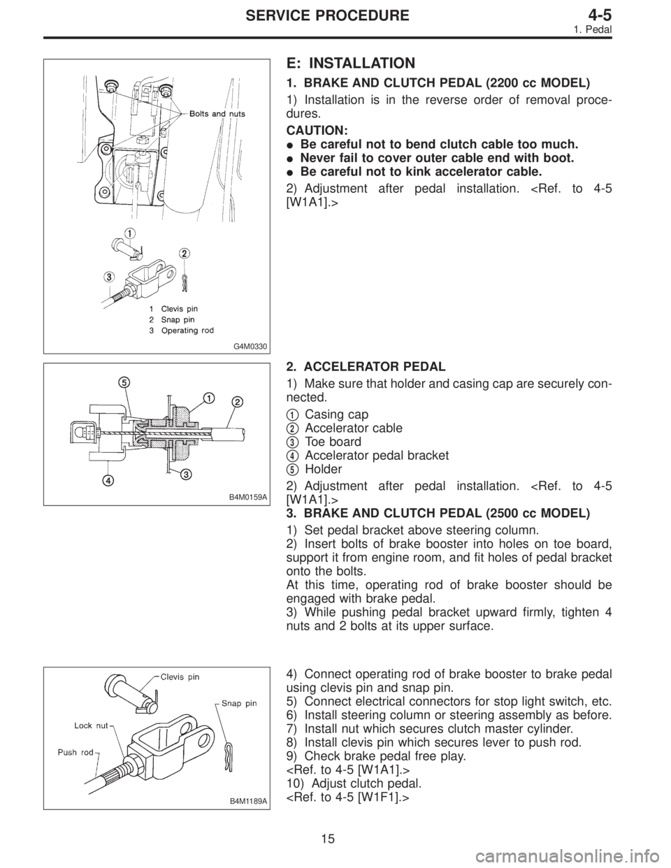
1. BRAKE AND CLUTCH PEDAL (2200 cc MODEL)
1) Installation is in the reverse order of removal proce-
dures.
CAUTION:
�Be careful not to bend clutch cable too much.
�Never fail to cover outer cable end with boot.
�Be careful not to kink accelerator cable.
2) Adjustment after pedal installation.
[W1A1].>
B4M0159A
2. ACCELERATOR PEDAL
1) Make sure that holder and casing cap are securely con-
nected.
�
1Casing cap
�
2Accelerator cable
�
3Toe board
�
4Accelerator pedal bracket
�
5Holder
2) Adjustment after pedal installation.
[W1A1].>
3. BRAKE AND CLUTCH PEDAL (2500 cc MODEL)
1) Set pedal bracket above steering column.
2) Insert bolts of brake booster into holes on toe board,
support it from engine room, and fit holes of pedal bracket
onto the bolts.
At this time, operating rod of brake booster should be
engaged with brake pedal.
3) While pushing pedal bracket upward firmly, tighten 4
nuts and 2 bolts at its upper surface.
B4M1189A
4) Connect operating rod of brake booster to brake pedal
using clevis pin and snap pin.
5) Connect electrical connectors for stop light switch, etc.
6) Install steering column or steering assembly as before.
7) Install nut which secures clutch master cylinder.
8) Install clevis pin which secures lever to push rod.
9) Check brake pedal free play.
10) Adjust clutch pedal.
15
4-5SERVICE PROCEDURE
1. Pedal
Page 1440 of 3342
1. Pedal System and Control Cables
Trouble Corrective action
Excessively worn brake pedal pad Replace.
Failure of clutch and/or accelerator pedals to operate Connect cables correctly.
Stop light switch does not light up. Adjust position of stop light switch.
Stop light switch is not smooth and/or stroke is not correct. Replace.
Insufficient pedal play Adjust pedal play.
Clutch and/or brake pedal free play insufficient Adjust pedal free play.
Maladjustment of brake pedal or booster push rod Inspect and adjust.
Excessively worn and damaged pedal shaft and/or bushing Replace bushing and/or shaft with new one.
20
4-5DIAGNOSTICS
1. Pedal System and Control Cables
Page 1463 of 3342

3. REFRIGERANT
Do not put CFC-12 refrigerant into a HFC-134a air condi-
tioning system. Also, do not put HFC-134a refrigerant into
a CFC-12 air conditioning system. If the wrong refrigerant
is used, poor lubrication will result and the compressor
itself may be destroyed.
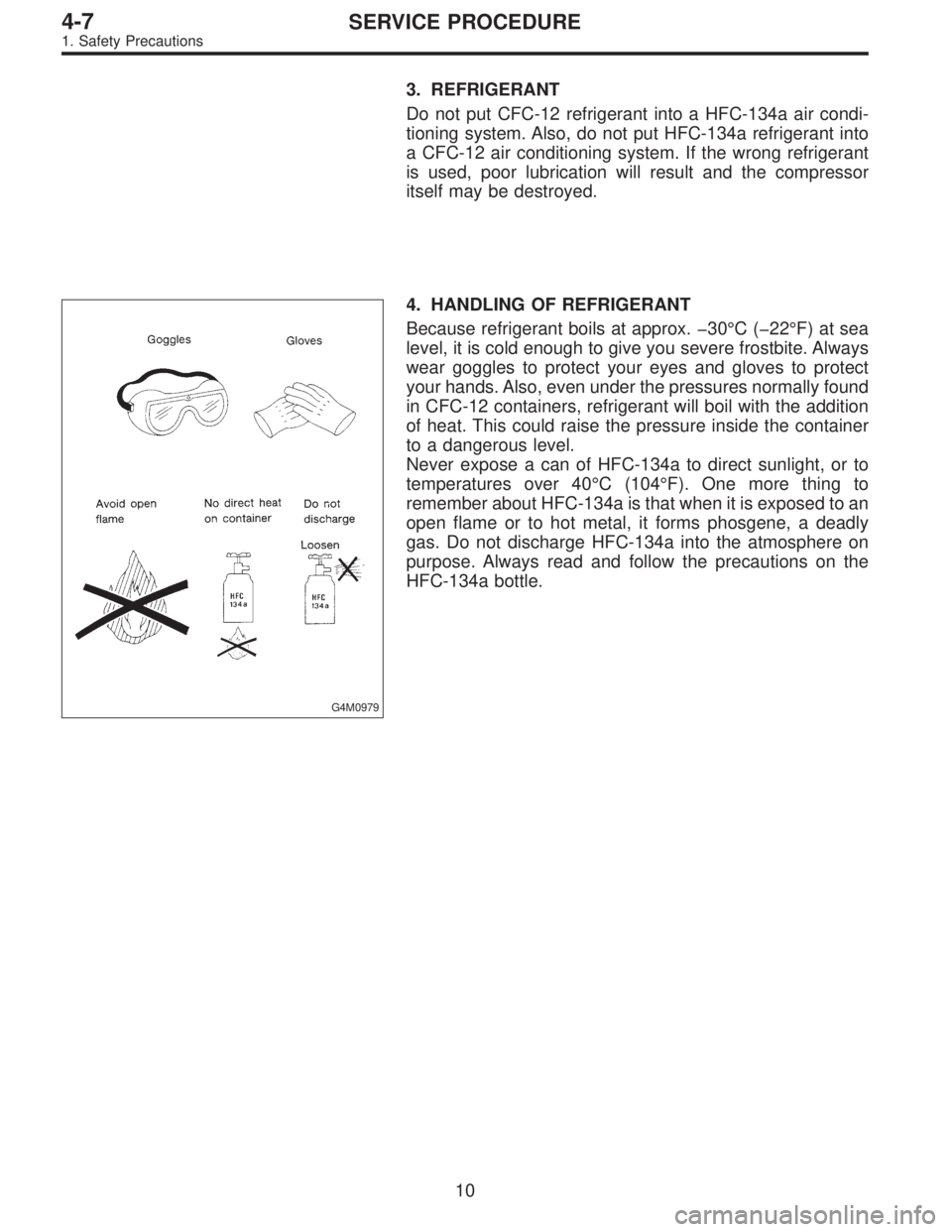
G4M0979
4. HANDLING OF REFRIGERANT
Because refrigerant boils at approx. �30°C (�22°F) at sea
level, it is cold enough to give you severe frostbite. Always
wear goggles to protect your eyes and gloves to protect
your hands. Also, even under the pressures normally found
in CFC-12 containers, refrigerant will boil with the addition
of heat. This could raise the pressure inside the container
to a dangerous level.
Never expose a can of HFC-134a to direct sunlight, or to
temperatures over 40°C (104°F). One more thing to
remember about HFC-134a is that when it is exposed to an
open flame or to hot metal, it forms phosgene, a deadly
gas. Do not discharge HFC-134a into the atmosphere on
purpose. Always read and follow the precautions on the
HFC-134a bottle.
10
4-7SERVICE PROCEDURE
1. Safety Precautions