Page 1401 of 3342
3. CONDITIONS FOR COMPLETION OF TCS
SEQUENCE CONTROL
When the following conditions develop, the TCS sequence
control stops and ABS and TCS warning lights come on
while the ABS and TCS function will then stop. The brake
system functions as a conventional brake system.
1) When the speed of at least one wheel reaches 10 km/h
(6 MPH).
2) When terminal No. 4 is separated from ground. (When
select monitor is not used.)
3) When the brake pedal is depressed during sequence
control and the braking lamp switch is set to ON.
4) When TCS OFF switch is released. (When select moni-
tor is not used.)
5) After completion of the TCS sequence control.
6) When output signal to break TCS control is emitted from
ECM.
7) When malfunction is detected.
NOTE:
When malfunction has been detected and the TCS
sequence control operation has stopped, the trouble codes
are stored in memory.
11 7
4-4SERVICE PROCEDURE
20. Hydraulic Unit for ABS/TCS System
Page 1411 of 3342
 Under the ABS sequence control, after the hydraulic
unit solenoid valve is driven, the operation of the hydraulic
unit can be checked by means of the brake tester or pres-
s")
D: ABS SEQUENCE CONTROL
1) Under the ABS sequence control, after the hydraulic
unit solenoid valve is driven, the operation of the hydraulic
unit can be checked by means of the brake tester or pres-
sure gauge.
2) ABS sequence control can be started by diagnosis con-
nector or select monitor.
B4M0082D
1. OPERATIONAL GUIDELINES OF THE ABS
SEQUENCE CONTROL WITH DIAGNOSIS
CONNECTOR
1) Connect diagnosis terminals to terminals No. 3 and No.
6 of the diagnosis connector beside driver’s seat heater
unit.
2) Set the speed of all wheels at 4 km/h (2 MPH) or less.
3) Turn ignition switch OFF.
4) Within 0.5 seconds after the ABS warning light goes
out, depress the brake pedal and hold it immediately after
ignition switch is turned to ON.
CAUTION:
Do not depress the clutch pedal.
NOTE:
�When the ignition switch is set to on, the brake pedal
must not be depressed.
�Engine must not operate.
5) After completion of ABS sequence control, turn ignition
switch OFF.
2. OPERATIONAL GUIDELINES OF THE ABS
SEQUENCE CONTROL WITH SELECT MONITOR
NOTE:
In the event of any trouble, the sequence control may not
be operative. In such a case, activate the sequence
control, referring to“OPERATIONAL GUIDELINES OF
THE ABS SEQUENCE CONTROL WITH DIAGNOSIS
CONNECTOR”.
1) Connect select monitor to data link connector beside
driver’s seat heater unit.
2) Turn ignition switch ON.
3) Put select monitor to ABS mode.
126
4-4SERVICE PROCEDURE
22. ABS Control Module and Hydraulic Control Unit (ABSCM&H/U) (ABS 5.3i Type)
Page 1413 of 3342
 After completion of ABS sequence control.
H4M1144
11) Press 0 key to start ABS sequence control again and
press 1 key to end.
3. CONDITIONS FOR COMPLETION OF ABS
SEQUENCE CONTROL
When the")
B4M1030
10) After completion of ABS sequence control.
H4M1144
11) Press 0 key to start ABS sequence control again and
press 1 key to end.
3. CONDITIONS FOR COMPLETION OF ABS
SEQUENCE CONTROL
When the following conditions develop, the ABS sequence
control stops and ABS operation is returned to the normal
control mode.
1) When the speed of at least one wheel reaches 10 km/h
(6 MPH).
2) When terminal No. 3 or No. 6 are separated from diag-
nosis terminals. (When select monitor is not used.)
3) When the brake pedal is released during sequence con-
trol and the braking lamp switch is set to off.
4) When brake pedal is depressed after ignition key is
turned to ON, and before ABS warning light goes out.
(When select monitor is not used.)
5) When brake pedal is not depressed after ignition key is
turned to ON, and within 0.5 seconds after ABS warning
light goes out. (When select monitor is not used.)
6) After completion of the sequence control.
7) When malfunction is detected. (When select monitor is
used.)
128
4-4SERVICE PROCEDURE
22. ABS Control Module and Hydraulic Control Unit (ABSCM&H/U) (ABS 5.3i Type)
Page 1422 of 3342
1. Pedal (MT Model)
1. 2200 cc MODEL
B4M0737A
�1Accelerator pedal
�
2Bushing
�
3Holder
�
4Accelerator bracket
�
5Stopper
�
6Clip
�
7Accelerator spring
�
8Accelerator pedal spring
�
9Spring pin
�
10Accelerator pedal pad
�
11Accelerator stopper
�
12Clip
�
13Accelerator plate�
14Pedal bracket
�
15Stop light switch (Without T.C.S.) /
stroke sensor (With T.C.S.)
�
16Brake pedal
�
17Spacer
�
18Snap pin
�
19Brake pedal pad
�
20Clevis pin
�
21Brake pedal spring
�
22Washer
�
23Clutch pedal pad
�
24Clutch pedal
�
25Bushing assist�
26Spring assist
�
27Clutch cable clamp
�
28Clutch cable
�
29Mass damper
�
30Clutch switch (Starter interlock)
�
31Clutch switch (With cruise control)
Tightening torque: N⋅m (kg-m, ft-lb)
T1: 5.9±1.5 (0.60±0.15, 4.3±1.1)
T2: 8±2 (0.8±0.2, 5.8±1.4)
T3: 18±5 (1.8±0.5, 13.0±3.6)
T4: 29±7 (3.0±0.7, 21.7±5.1)
3
4-5COMPONENT PARTS
1. Pedal (MT Model)
Page 1423 of 3342
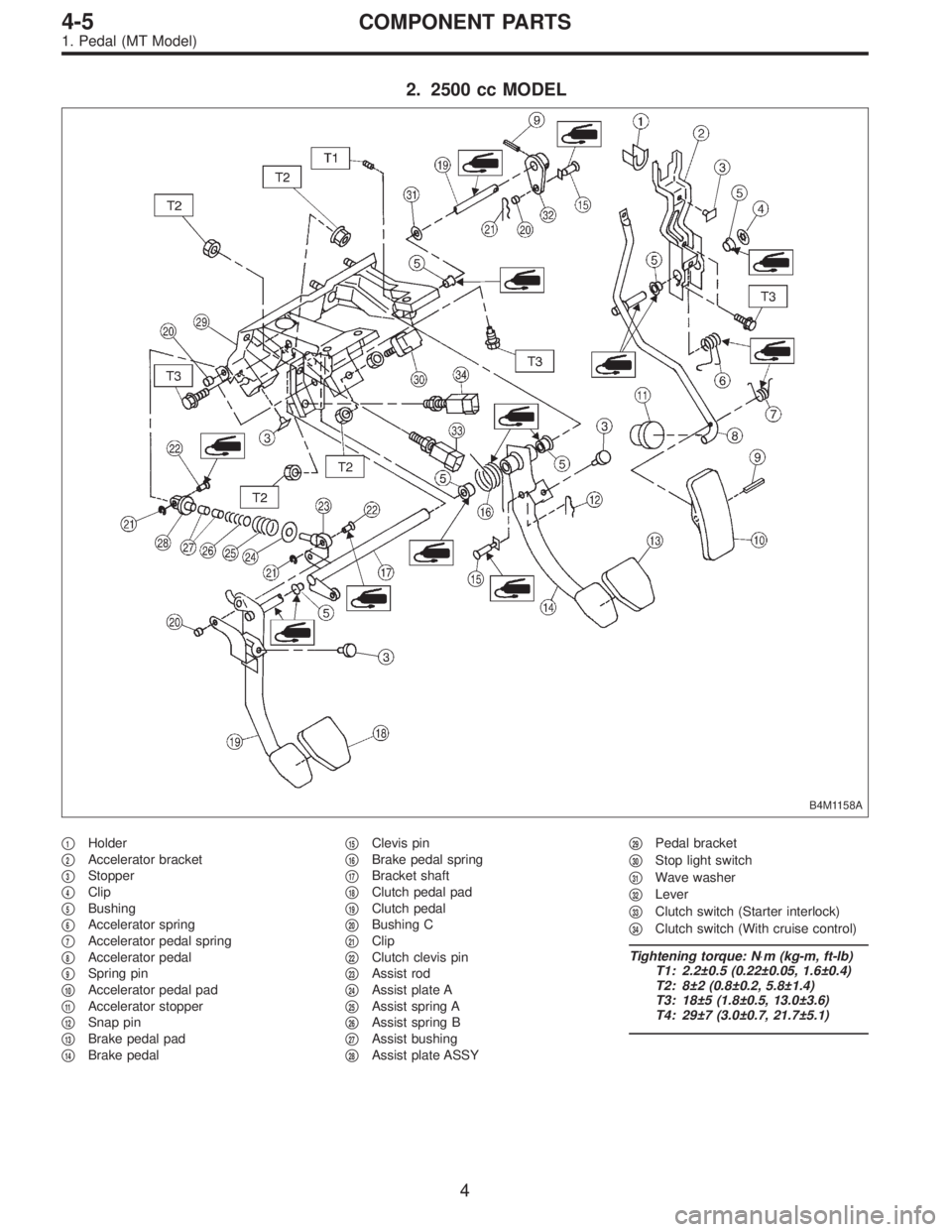
2. 2500 cc MODEL
B4M1158A
�1Holder
�
2Accelerator bracket
�
3Stopper
�
4Clip
�
5Bushing
�
6Accelerator spring
�
7Accelerator pedal spring
�
8Accelerator pedal
�
9Spring pin
�
10Accelerator pedal pad
�
11Accelerator stopper
�
12Snap pin
�
13Brake pedal pad
�
14Brake pedal�
15Clevis pin
�
16Brake pedal spring
�
17Bracket shaft
�
18Clutch pedal pad
�
19Clutch pedal
�
20Bushing C
�
21Clip
�
22Clutch clevis pin
�
23Assist rod
�
24Assist plate A
�
25Assist spring A
�
26Assist spring B
�
27Assist bushing
�
28Assist plate ASSY�
29Pedal bracket
�
30Stop light switch
�
31Wave washer
�
32Lever
�
33Clutch switch (Starter interlock)
�
34Clutch switch (With cruise control)
Tightening torque: N⋅m (kg-m, ft-lb)
T1: 2.2±0.5 (0.22±0.05, 1.6±0.4)
T2: 8±2 (0.8±0.2, 5.8±1.4)
T3: 18±5 (1.8±0.5, 13.0±3.6)
T4: 29±7 (3.0±0.7, 21.7±5.1)
4
4-5COMPONENT PARTS
1. Pedal (MT Model)
Page 1424 of 3342
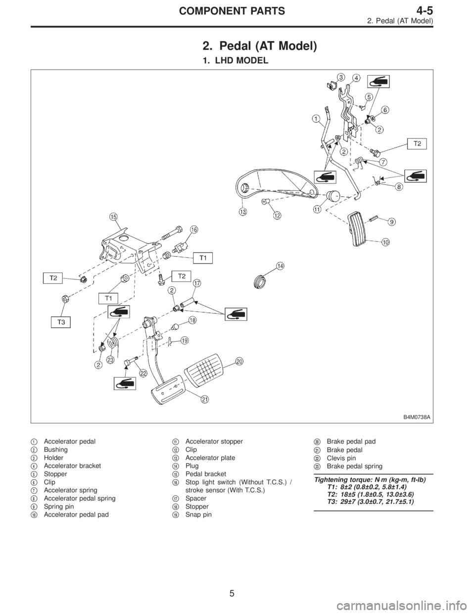
2. Pedal (AT Model)
1. LHD MODEL
B4M0738A
�1Accelerator pedal
�
2Bushing
�
3Holder
�
4Accelerator bracket
�
5Stopper
�
6Clip
�
7Accelerator spring
�
8Accelerator pedal spring
�
9Spring pin
�
10Accelerator pedal pad�
11Accelerator stopper
�
12Clip
�
13Accelerator plate
�
14Plug
�
15Pedal bracket
�
16Stop light switch (Without T.C.S.) /
stroke sensor (With T.C.S.)
�
17Spacer
�
18Stopper
�
19Snap pin�
20Brake pedal pad
�
21Brake pedal
�
22Clevis pin
�
23Brake pedal spring
Tightening torque: N⋅m (kg-m, ft-lb)
T1: 8±2 (0.8±0.2, 5.8±1.4)
T2: 18±5 (1.8±0.5, 13.0±3.6)
T3: 29±7 (3.0±0.7, 21.7±5.1)
5
4-5COMPONENT PARTS
2. Pedal (AT Model)
Page 1425 of 3342
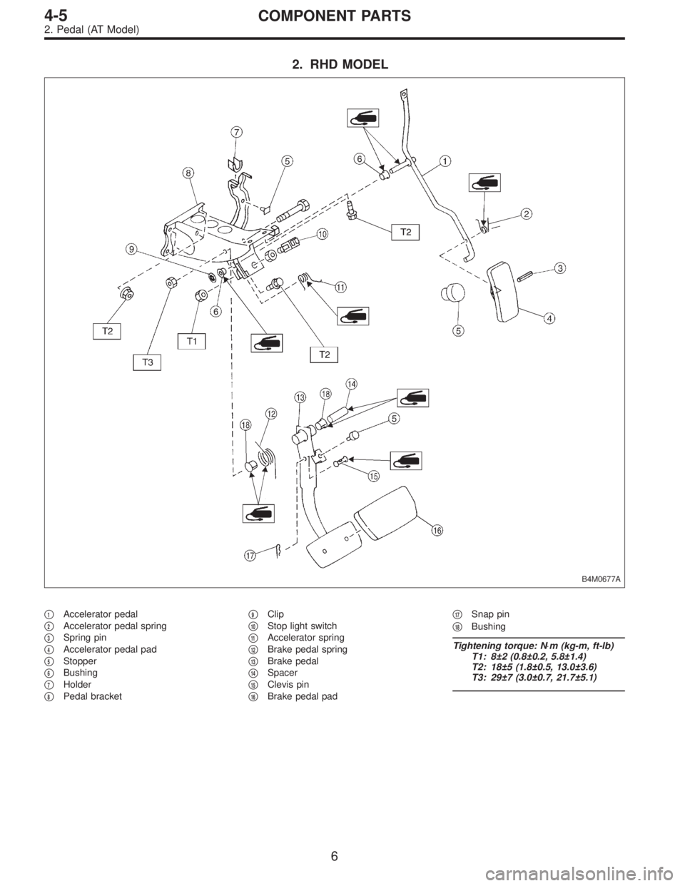
2. RHD MODEL
B4M0677A
�1Accelerator pedal
�
2Accelerator pedal spring
�
3Spring pin
�
4Accelerator pedal pad
�
5Stopper
�
6Bushing
�
7Holder
�
8Pedal bracket�
9Clip
�
10Stop light switch
�
11Accelerator spring
�
12Brake pedal spring
�
13Brake pedal
�
14Spacer
�
15Clevis pin
�
16Brake pedal pad�
17Snap pin
�
18Bushing
Tightening torque: N⋅m (kg-m, ft-lb)
T1: 8±2 (0.8±0.2, 5.8±1.4)
T2: 18±5 (1.8±0.5, 13.0±3.6)
T3: 29±7 (3.0±0.7, 21.7±5.1)
6
4-5COMPONENT PARTS
2. Pedal (AT Model)
Page 1426 of 3342
 Check position of pedal pad.
�
1Stop light switch
�
2Mat
�
3Toe board
�
4Brake booster operating rod
Pedal height: L
148 mm (5.83 in)
If it is not")
B4M0366A
1. Pedal
A: ON-CAR SERVICE
1. BRAKE PEDAL
1) Check position of pedal pad.
�
1Stop light switch
�
2Mat
�
3Toe board
�
4Brake booster operating rod
Pedal height: L
148 mm (5.83 in)
If it is not in specified value, adjust it by adjusting brake
booster operating rod length.
2) Check free play by operating pedal by hand.
If it is not in specified value, adjust it by adjusting position
of stop light switch.
CAUTION:
Be careful not to rotate stop light switch.
Brake pedal free play: A
1 — 3 mm (0.04 — 0.12 in)
[Depress brake pedal pad with a force of less than
10 N (1 kg, 2 lb).]
Stop light switch lock nut tightening torque:
8±2 N⋅m (0.8±0.2 kg-m, 5.8±1.4 ft-lb)
3) Apply grease to operating rod connecting pin to prevent
it from wearing.
G4M0318
2. CLUTCH PEDAL (2200 cc MODEL)
1) Check clutch pedal free play by operating pedal by
hand.
Free play: L (At clutch pedal pad)
10 — 20 mm (0.39 — 0.79 in)
B4M0367A
Pedal height: Y
158 mm (6.22 in)
Pedal stroke: A
140 — 145 mm (5.51 — 5.71 in)
�
1Toe board
�
2Mat
7
4-5SERVICE PROCEDURE
1. Pedal