Page 1547 of 3342
4. Front Bumper
A: REMOVAL
SUPPLEMENTAL RESTRAINT SYSTEM“AIRBAG”
Airbag system wiring harness is routed near the front
bumper assembly.
CAUTION:
�All Airbag system wiring harness and connectors
are colored yellow. Do not use electrical test equip-
ment on these circuits.
�Be careful not to damage Airbag system wiring har-
ness when servicing the front bumper assembly.
B5M0273
1. EXCEPT OUTBACK WITH STEP ROOF
1) Disconnect the ground cable from the battery.
2) Remove two bolts from lower center of bumper.
3) Remove mud guard.
NOTE:
It is not necessary to remove the entire mud guard.
Remove clips from the front section of mud guard, if nec-
essary.
4) Remove the canister.
B5M0274
5) Remove two bolts from side of bumper.
6) Remove front grill.
7) Remove headlight.
B5M0376
8) Remove clips from both sides of front bumper.
NOTE:
When removing, push the pin at the center of clip with a
thin screwdriver.
38
5-1SERVICE PROCEDURE
4. Front Bumper
Page 1548 of 3342
B5M0275
9) Remove bolts (engine compartment side) from bumper
stays.
B5M0276
10) Remove front bumper assembly.
NOTE:
Front bumper surface is accessible for removal after
removing the following parts:
Two bolts (on the lower center of bumper), mud guard,
bolts (on the side of bumper), front grille, headlight, clips
(on both sides of front bumper), clips (on the upper section
of bumper), and clips (on the lower section of bumper).
G6M0095
2. OUTBACK WITH STEP ROOF
1) Disconnect the ground cable from the battery.
B5M0273
2) Remove two bolts from lower center of bumper.
3) Remove mud guard.
NOTE:
It is not necessary to remove the entire mud guard.
Remove clips from the front section of mud guard, if nec-
essary.
4) Remove the canister.
B5M0274
5) Remove two bolts from side of bumper.
6) Remove front grill.
7) Remove headlight.
39
5-1SERVICE PROCEDURE
4. Front Bumper
Page 1549 of 3342
 Remove fog lamps.
9) Remove clips from both sides of front bumper.
NOTE:
When removing, push the pin at the center of clip with a
thin screwdriver.
B5M0275
10) Remove bolts (engine compartm")
B5M0376
8) Remove fog lamps.
9) Remove clips from both sides of front bumper.
NOTE:
When removing, push the pin at the center of clip with a
thin screwdriver.
B5M0275
10) Remove bolts (engine compartment side) from
bumper stays.
B5M0406
11) Remove front bumper assembly.
NOTE:
Front bumper surface is accessible for removal after
removing the following parts:
Two bolts (on the lower center of bumper), mud guard,
bolts (on the side of bumper), front grille, headlight, clips
(on both sides of front bumper), clips (on the upper section
of bumper), and clips (on the lower section of bumper).
B5M0375A
B: INSTALLATION
1. EXCEPT OUTBACK WITH STEP ROOF
To install the front bumper, reverse the above removal pro-
cedures.
CAUTION:
�Be extremely careful to prevent scratches on
bumper face as it is made of resin.
�Be careful not to scratch the body when removing or
installing the bumper.
�When installing canister, insert air vent hose of can-
ister into the hole on body.
�To facilitate installation of front bumper, insert the
protrusion inside bumper into the groove of body.
40
5-1SERVICE PROCEDURE
4. Front Bumper
Page 1556 of 3342

7. Repair Instructions for Colored PP
Bumper
All PP bumpers are provided with a grained surface, and if
the surface is damaged, it cannot normally be restored to
its former condition. Damage limited to shallow scratches
that cause only a change in the lustre of the base material
or coating, can be almost fully restored. Before repairing a
damaged area, explain this point to the customer and get
an understanding about the matter.
Repair methods are outlined below, based on a classifica-
tion of the extent of damage.
1. MINOR DAMAGE CAUSING ONLY A CHANGE IN
THE LUSTRE OF THE BUMPER DUE TO A LIGHT
TOUCH
It is almost restorable as follows:
Process
No.Process name Job contents
1 Cleaning Clean the area to be repaired using water.
2 Sanding Grind the repairing area with #500 sand paper in a“feathering”motion.
3 FinishResin section Coated section
Repeatedly apply wax to the affected area using
a soft cloth (such as flannel).
Recommended wax: NITTO KASEI Soft 99 TIRE
WAX BLACK, or equivalent.Perform either the same operation as for the
resin section or process No. 18 and subsequent
operations in the“3.”section, depending on the
degree and nature of damage.
Polish the waxed area with a clean cloth after 5
to 10 minutes.
2. DEEP DAMAGE CAUSED BY SCRATCHING
FENCES, ETC.
A dent cannot be repaired but a whitened or swelled part
can be removed.
Process
No.Process name Job contents
1 Cleaning Clean damaged area with water.
2Removal of dam-
aged areaCut off protruding area, if any, due to collision, using a putty knife.
3 Sanding Grind the affected area with #100 to #500 sand paper.
4 FinishResin section Coated section
Same as process No. 3 in the“1.”section.Perform process No. 12 and subsequent opera-
tions in the“3.”section.
46
5-1SERVICE PROCEDURE
7. Repair Instructions for Colored PP Bumper
Page 1560 of 3342
8. Front Fender
A: REMOVAL
SUPPLEMENTAL RESTRAINT SYSTEM“AIRBAG”
Airbag system wiring harness is routed near the front
fender.
CAUTION:
�All Airbag system wiring harness and connectors
are colored yellow. Do not use electrical test equip-
ment on these circuits.
�Be careful not to damage Airbag system wiring har-
ness when servicing the front fender.
B5M0285A
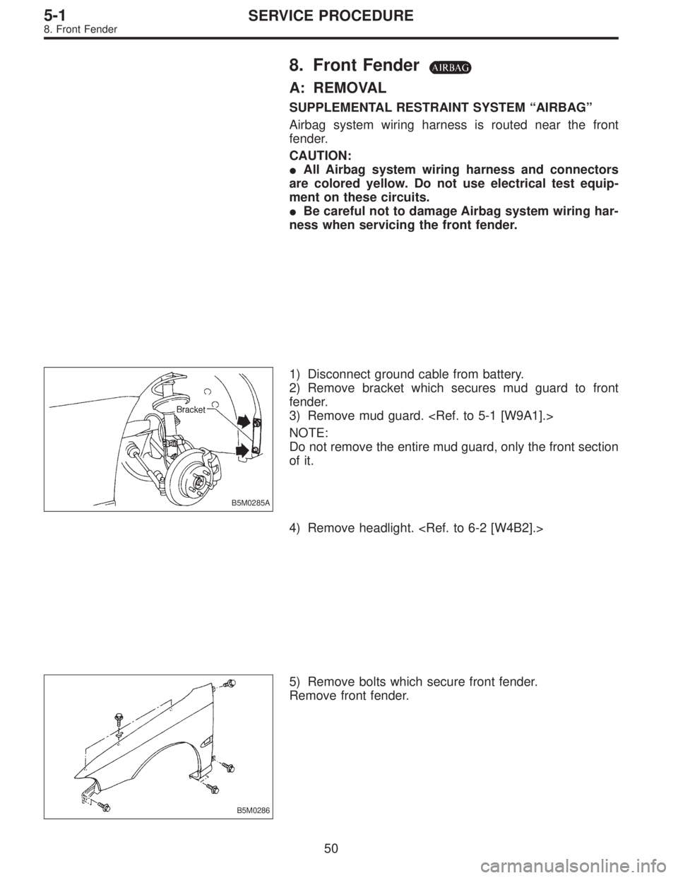
1) Disconnect ground cable from battery.
2) Remove bracket which secures mud guard to front
fender.
3) Remove mud guard.
NOTE:
Do not remove the entire mud guard, only the front section
of it.
4) Remove headlight.
B5M0286
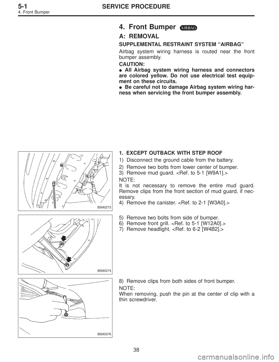
5) Remove bolts which secure front fender.
Remove front fender.
50
5-1SERVICE PROCEDURE
8. Front Fender
Page 1565 of 3342
B: INSTALLATION
Installation is in the reverse order of removal.
NOTE:
When installing cowl panel, first attach a middle clip to the
cap attached to body panel. Then tap the cowl panel to
attach it to other clips.
B5M0292
11. Molding and Retainer
A: REMOVAL
1) Remove weatherstrip.
2) Remove tapping screws.
B5M0293A
B: INSTALLATION
Installation is in the reverse order of removal.
NOTE:
Insert molding and retainer onto hook, then fasten with
screws.
B5M0294A
12. Front Grille
A: REMOVAL
1) Remove four upper clips from body panel. To facilitate
removal, press portion shown in figure using screwdriver.
2) Pull front grille to detach it from two lower clips.
(Two lower clips remain on headlight.)
B: INSTALLATION
Attach all clips to grille. Align them with clip hole in body
and push them into place.
53
5-1SERVICE PROCEDURE
10. Cowl Panel - 12. Front Grille
Page 1566 of 3342
B: INSTALLATION
Installation is in the reverse order of removal.
NOTE:
When installing cowl panel, first attach a middle clip to the
cap attached to body panel. Then tap the cowl panel to
attach it to other clips.
B5M0292
11. Molding and Retainer
A: REMOVAL
1) Remove weatherstrip.
2) Remove tapping screws.
B5M0293A
B: INSTALLATION
Installation is in the reverse order of removal.
NOTE:
Insert molding and retainer onto hook, then fasten with
screws.
B5M0294A
12. Front Grille
A: REMOVAL
1) Remove four upper clips from body panel. To facilitate
removal, press portion shown in figure using screwdriver.
2) Pull front grille to detach it from two lower clips.
(Two lower clips remain on headlight.)
B: INSTALLATION
Attach all clips to grille. Align them with clip hole in body
and push them into place.
53
5-1SERVICE PROCEDURE
10. Cowl Panel - 12. Front Grille
Page 1567 of 3342
B: INSTALLATION
Installation is in the reverse order of removal.
NOTE:
When installing cowl panel, first attach a middle clip to the
cap attached to body panel. Then tap the cowl panel to
attach it to other clips.
B5M0292
11. Molding and Retainer
A: REMOVAL
1) Remove weatherstrip.
2) Remove tapping screws.
B5M0293A
B: INSTALLATION
Installation is in the reverse order of removal.
NOTE:
Insert molding and retainer onto hook, then fasten with
screws.
B5M0294A
12. Front Grille
A: REMOVAL
1) Remove four upper clips from body panel. To facilitate
removal, press portion shown in figure using screwdriver.
2) Pull front grille to detach it from two lower clips.
(Two lower clips remain on headlight.)
B: INSTALLATION
Attach all clips to grille. Align them with clip hole in body
and push them into place.
53
5-1SERVICE PROCEDURE
10. Cowl Panel - 12. Front Grille
 Remove bolts (engine compartment side) from bumper
stays.
B5M0276
10) Remove front bumper assembly.
NOTE:
Front bumper surface is accessible for removal after
removing the following parts:")