Page 3319 of 3342

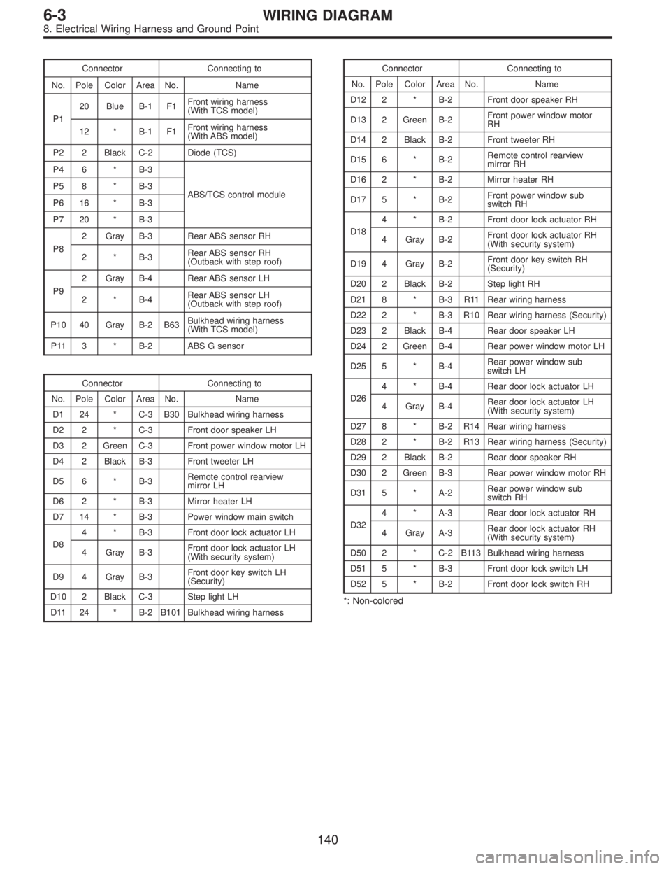
Connector Connecting to
No. Pole Color Area No. Name
P120 Blue B-1 F1Front wiring harness
(With TCS model)
12 * B-1 F1Front wiring harness
(With ABS model)
P2 2 Black C-2 Diode (TCS)
P4 6 * B-3
ABS/TCS control module P5 8 * B-3
P6 16 * B-3
P7 20 * B-3
P82 Gray B-3 Rear ABS sensor RH
2*B-3Rear ABS sensor RH
(Outback with step roof)
P92 Gray B-4 Rear ABS sensor LH
2*B-4Rear ABS sensor LH
(Outback with step roof)
P10 40 Gray B-2 B63Bulkhead wiring harness
(With TCS model)
P11 3 * B-2 ABS G sensor
Connector Connecting to
No. Pole Color Area No. Name
D1 24 * C-3 B30 Bulkhead wiring harness
D2 2 * C-3 Front door speaker LH
D3 2 Green C-3 Front power window motor LH
D4 2 Black B-3 Front tweeter LH
D5 6 * B-3Remote control rearview
mirror LH
D6 2 * B-3 Mirror heater LH
D7 14 * B-3 Power window main switch
D84 * B-3 Front door lock actuator LH
4 Gray B-3Front door lock actuator LH
(With security system)
D9 4 Gray B-3Front door key switch LH
(Security)
D10 2 Black C-3 Step light LH
D11 24 * B-2 B101 Bulkhead wiring harness
Connector Connecting to
No. Pole Color Area No. Name
D12 2 * B-2 Front door speaker RH
D13 2 Green B-2Front power window motor
RH
D14 2 Black B-2 Front tweeter RH
D15 6 * B-2Remote control rearview
mirror RH
D16 2 * B-2 Mirror heater RH
D17 5 * B-2Front power window sub
switch RH
D184 * B-2 Front door lock actuator RH
4 Gray B-2Front door lock actuator RH
(With security system)
D19 4 Gray B-2Front door key switch RH
(Security)
D20 2 Black B-2 Step light RH
D21 8 * B-3 R11 Rear wiring harness
D22 2 * B-3 R10 Rear wiring harness (Security)
D23 2 Black B-4 Rear door speaker LH
D24 2 Green B-4 Rear power window motor LH
D25 5 * B-4Rear power window sub
switch LH
D264 * B-4 Rear door lock actuator LH
4 Gray B-4Rear door lock actuator LH
(With security system)
D27 8 * B-2 R14 Rear wiring harness
D28 2 * B-2 R13 Rear wiring harness (Security)
D29 2 Black B-2 Rear door speaker RH
D30 2 Green B-3 Rear power window motor RH
D31 5 * A-2Rear power window sub
switch RH
D324 * A-3 Rear door lock actuator RH
4 Gray A-3Rear door lock actuator RH
(With security system)
D50 2 * C-2 B113 Bulkhead wiring harness
D51 5 * B-3 Front door lock switch LH
D52 5 * B-2 Front door lock switch RH
*: Non-colored
140
6-3WIRING DIAGRAM
8. Electrical Wiring Harness and Ground Point
Page 3323 of 3342

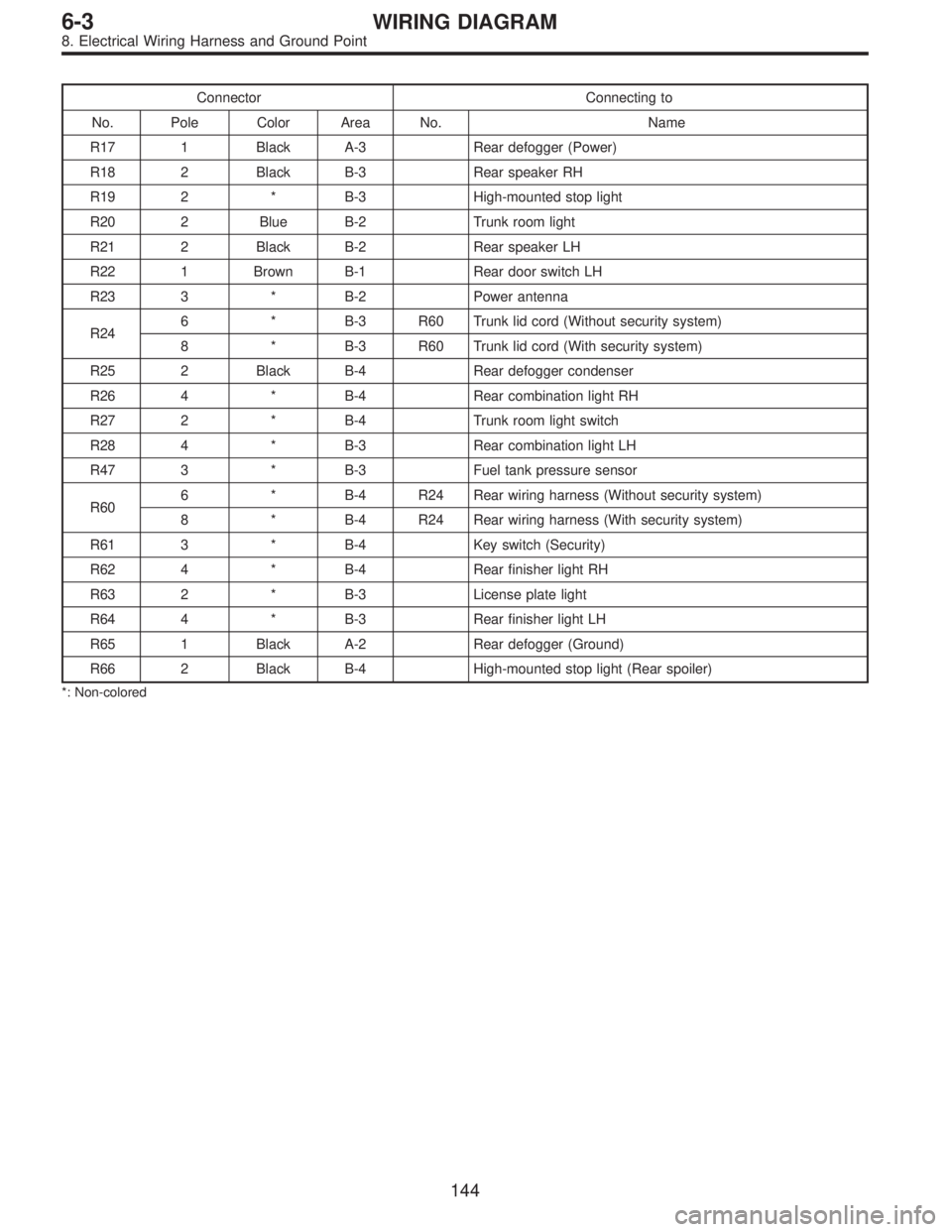
Connector Connecting to
No. Pole Color Area No. Name
R17 1 Black A-3 Rear defogger (Power)
R18 2 Black B-3 Rear speaker RH
R19 2 * B-3 High-mounted stop light
R20 2 Blue B-2 Trunk room light
R21 2 Black B-2 Rear speaker LH
R22 1 Brown B-1 Rear door switch LH
R23 3 * B-2 Power antenna
R246 * B-3 R60 Trunk lid cord (Without security system)
8 * B-3 R60 Trunk lid cord (With security system)
R25 2 Black B-4 Rear defogger condenser
R26 4 * B-4 Rear combination light RH
R27 2 * B-4 Trunk room light switch
R28 4 * B-3 Rear combination light LH
R47 3 * B-3 Fuel tank pressure sensor
R606 * B-4 R24 Rear wiring harness (Without security system)
8 * B-4 R24 Rear wiring harness (With security system)
R61 3 * B-4 Key switch (Security)
R62 4 * B-4 Rear finisher light RH
R63 2 * B-3 License plate light
R64 4 * B-3 Rear finisher light LH
R65 1 Black A-2 Rear defogger (Ground)
R66 2 Black B-4 High-mounted stop light (Rear spoiler)
*: Non-colored
144
6-3WIRING DIAGRAM
8. Electrical Wiring Harness and Ground Point
Page 3325 of 3342

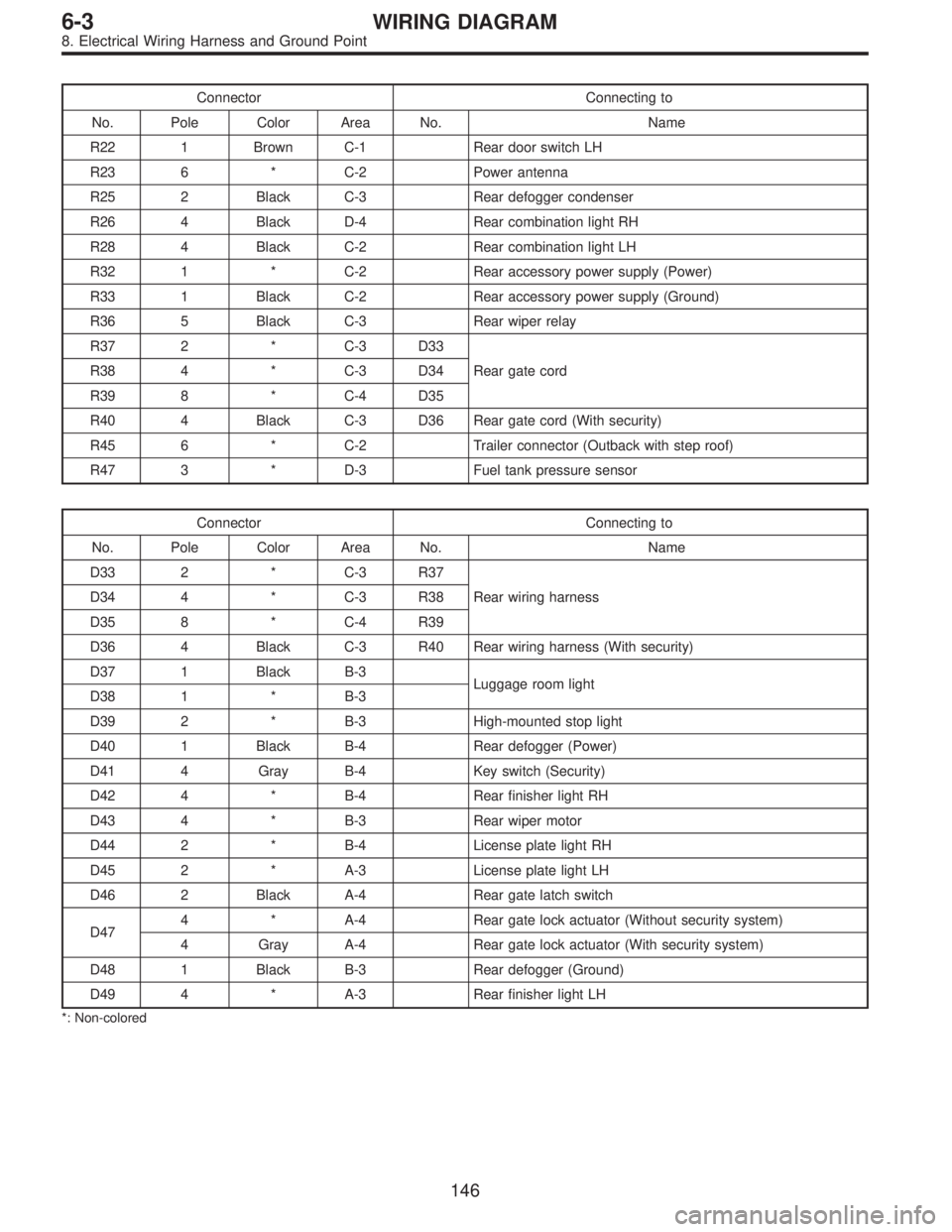
Connector Connecting to
No. Pole Color Area No. Name
R22 1 Brown C-1 Rear door switch LH
R23 6 * C-2 Power antenna
R25 2 Black C-3 Rear defogger condenser
R26 4 Black D-4 Rear combination light RH
R28 4 Black C-2 Rear combination light LH
R32 1 * C-2 Rear accessory power supply (Power)
R33 1 Black C-2 Rear accessory power supply (Ground)
R36 5 Black C-3 Rear wiper relay
R37 2 * C-3 D33
Rear gate cord R38 4 * C-3 D34
R39 8 * C-4 D35
R40 4 Black C-3 D36 Rear gate cord (With security)
R45 6 * C-2 Trailer connector (Outback with step roof)
R47 3 * D-3 Fuel tank pressure sensor
Connector Connecting to
No. Pole Color Area No. Name
D33 2 * C-3 R37
Rear wiring harness D34 4 * C-3 R38
D35 8 * C-4 R39
D36 4 Black C-3 R40 Rear wiring harness (With security)
D37 1 Black B-3
Luggage room light
D38 1 * B-3
D39 2 * B-3 High-mounted stop light
D40 1 Black B-4 Rear defogger (Power)
D41 4 Gray B-4 Key switch (Security)
D42 4 * B-4 Rear finisher light RH
D43 4 * B-3 Rear wiper motor
D44 2 * B-4 License plate light RH
D45 2 * A-3 License plate light LH
D46 2 Black A-4 Rear gate latch switch
D474 * A-4 Rear gate lock actuator (Without security system)
4 Gray A-4 Rear gate lock actuator (With security system)
D48 1 Black B-3 Rear defogger (Ground)
D49 4 * A-3 Rear finisher light LH
*: Non-colored
146
6-3WIRING DIAGRAM
8. Electrical Wiring Harness and Ground Point
Page 3327 of 3342
Connector Connecting to
No. Pole Color Area No. Name
R22 1 Brown C-1 Rear door switch LH
R23 6 * C-2 Power antenna
R25 2 Black C-3 Rear defogger condenser
R26 4 Black D-4 Rear combination light RH
R28 4 Black C-2 Rear combination light LH
R36 5 Black C-3 Rear wiper relay
R37 2 * C-3 D33
Rear gate cord R38 4 * C-3 D34
R39 8 * C-4 D35
R47 3 * D-3 Fuel tank pressure sensor
Connector Connecting to
No. Pole Color Area No. Name
D33 2 * C-3 R37
Rear wiring harness D34 4 * C-3 R38
D35 8 * C-4 R39
D37 1 Black B-3
Luggage room light
D38 1 * B-3
D39 2 * B-3 High-mounted stop light
D40 1 Black B-4 Rear defogger (Power)
D42 4 * B-4 Rear finisher light RH
D43 4 * B-3 Rear wiper motor
D44 2 * B-4 License plate light RH
D45 2 * A-3 License plate light LH
D46 2 Black A-4 Rear gate latch switch
D47 4 * A-4 Rear gate lock actuator
D48 1 Black B-3 Rear defogger (Ground)
D49 4 * A-3 Rear finisher light LH
*: Non-colored
148
6-3WIRING DIAGRAM
8. Electrical Wiring Harness and Ground Point
Page 3337 of 3342

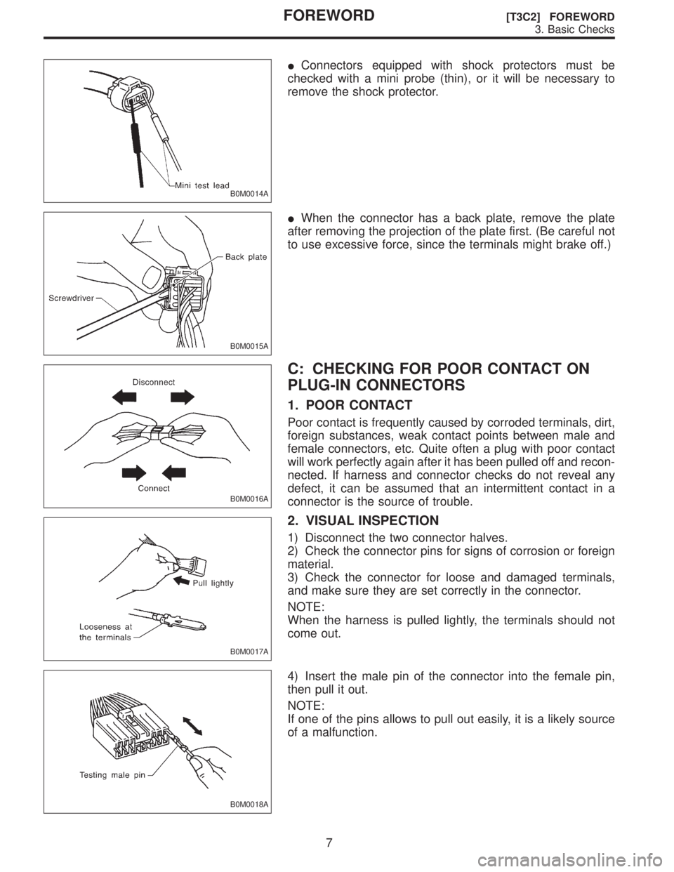
B0M0014A
�Connectors equipped with shock protectors must be
checked with a mini probe (thin), or it will be necessary to
remove the shock protector.
B0M0015A
�When the connector has a back plate, remove the plate
after removing the projection of the plate first. (Be careful not
to use excessive force, since the terminals might brake off.)
B0M0016A
C: CHECKING FOR POOR CONTACT ON
PLUG-IN CONNECTORS
1. POOR CONTACT
Poor contact is frequently caused by corroded terminals, dirt,
foreign substances, weak contact points between male and
female connectors, etc. Quite often a plug with poor contact
will work perfectly again after it has been pulled off and recon-
nected. If harness and connector checks do not reveal any
defect, it can be assumed that an intermittent contact in a
connector is the source of trouble.
B0M0017A
2. VISUAL INSPECTION
1) Disconnect the two connector halves.
2) Check the connector pins for signs of corrosion or foreign
material.
3) Check the connector for loose and damaged terminals,
and make sure they are set correctly in the connector.
NOTE:
When the harness is pulled lightly, the terminals should not
come out.
B0M0018A
4) Insert the male pin of the connector into the female pin,
then pull it out.
NOTE:
If one of the pins allows to pull out easily, it is a likely source
of a malfunction.
7
[T3C2] FOREWORDFOREWORD
3. Basic Checks
Page 3338 of 3342
B0M0019A
5) Shake lightly the connector and the harness, and check for
sudden changes in voltage or resistance.
8
FOREWORD [T3C2]FOREWORD
3. Basic Checks