Page 3187 of 3342

2. Basic Diagnostics Procedures
The most important purpose of diagnostics is to determine
which part is malfunctioning quickly, to save time and labor.
A: IDENTIFICATION OF TROUBLE SYMPTOM
Determine what the problem is based on the symptom.
B: PROBABLE CAUSE OF TROUBLE
Look at the wiring diagram and check the system’s circuit.
Then check the switch, relay, fuse, ground, etc.
C: LOCATION AND REPAIR OF TROUBLE
1) Using the diagnostics narrow down the causes.
2) If necessary, use a voltmeter, ohmmeter, etc.
3) Before replacing certain component parts (switch, relay,
etc.), check the power supply, ground, for open wiring
harness, poor connectors, etc. If no problems are
encountered, check the component parts.
D: CONFIRMATION OF SYSTEM OPERATION
After repairing, ensure that the system operates properly.
G6M0206
E: INSPECTION
1. VOLTAGE MEASUREMENT
1) Using a voltmeter, connect the negative lead to a good
ground point or negative battery terminal and the positive
lead to the connector or component terminal.
2) Contact the positive probe of the voltmeter on connec-
tor (A).
The voltmeter will indicate a voltage.
3) Shift the positive probe to connector (B). The voltmeter
will indicate no voltage.
With test set-up held as it is, turn switch ON. The voltme-
ter will indicate a voltage and, at the same time, the light
will come on.
4) The circuit is in good order. If a problem such as a lamp
failing to light occurs, use the procedures outlined above to
track down the malfunction.
8
6-3WIRING DIAGRAM
2. Basic Diagnostics Procedures
Page 3196 of 3342
ABBREVIATION LIST
Abbr. Full name
A.B.S. Antilock Brake System
ACC Accessory
A/C Air Conditioning
AD Auto Down
AT Automatic Transmission
AU Auto Up
+B Battery
DN Down
DRL Daytime Running Light
E Ground
F/B Fuse & Joint Box
FL1.5 Fusible link 1.5 mm
2
IG Ignition
Illumi. Illumination
Abbr. Full name
LH Left Hand
Lo Low
M Motor
M/B Main Fuse Box
MG Magnet
Mi Middle
OP Optional Parts
PASS Passing
RH Right Hand
SBF Slow Blow Fuse
S.M.J. Super Multiple Junction
ST Starter
SW Switch
T.C.S. Traction Control System
UP Up
WASH Washer
17
6-3WIRING DIAGRAM
5. How to Use Super Multiple Junction (S.M.J.)
Page 3199 of 3342

MB-2 Power window circuit breaker
MB-3Engine control module
Fuel pump relay
Main relay
OBD-II service connector
MB-4 A/C relay holder
MB-5 He")
No. Load
MB-1Fuse holder (Rear power supply & seat
heater)
MB-2 Power window circuit breaker
MB-3Engine control module
Fuel pump relay
Main relay
OBD-II service connector
MB-4 A/C relay holder
MB-5 Headlight alarm relay (with security)
MB-6 Headlight LH
MB-7Daytime running light control module
Diode (Lighting)
Diode (Security)
Lighting switch
MB-8Combination meter
Front fog light switch
Headlight RH
Front fog light relay
MB-9Door lock timer
Headlight alarm relay
Interrupt relay
Radio
Security control module
Security indicator light
Spot light
Room light
Step light
Combination meter
Luggage room light
Trailer connector
Trunk room light
MB-10 A/C relay holder
SBF-6ABS relay box
TCS motor relay
SBF-7 TCS valve relay
ALT-1Combination meter
Daytime running light control module
Diode (TCS)
IG Headlight alarm relay
STCruise control module
Engine control module
Inhibitor switch (AT)
Interrupt relay
Starter interlock relay (MT)
FB-1Front washer motor
Rear washer motor
FB-2Engine control module
Main fan relay 1
FB-3Sub fan relay 2
Sub fan motor
FB-4Engine control module
Fuel pump relay
Ignition coil
Transmission control moduleNo. Load
FB-5 ABS relay box
FB-6Side marker light LH
Side marker light RH
FB-7 Door lock timer
FB-9 Hazard switch
FB-10AT shift lock control module
Key warning switch
Power antenna
FB-11 Radio
FB-12 Front accessory power supply
FB-13Mirror heater
Rear power supply relay
Remote control rearview mirror switch
Security control module
Vanity mirror illumination light
FB-14AT shift lock control module
Combination switch
Front wiper motor
Rear wiper motor
Rear wiper relay
FB-15ABS/TCS control module
Transmission control module
FB-16Rear defogger
Rear defogger condenser
Rear defogger switch
FB-17 Rear defogger switch
FB-18AT shift lock control module
Back-up light switch (MT)
Inhibitor switch (AT)
FB-19 Hazard switch
FB-20A/C switch
Combination meter
Mode control panel
TCS off switch
FB-22Blower motor relay
Check connector
Daytime running light control module
Daytime running light relay
FRESH/RECIRC actuator
Hi-beam relay
Power window and sunroof relay
Seat belt timer
FB-23 Airbag control module
FB-24 Airbag control module
FB-25 Lighting switch
20
6-3WIRING DIAGRAM
6. Wiring Diagram
Page 3200 of 3342
No. Load
FB-26 Parking switch
FB-27 Parking switch
FB-28 Illumination light
FB-29 Illumination light
FB-30Pedal stroke switch
Stop light switch
Stop & brake switch
FB-31 Horn relay
FB-32 Blower motor relay
FB-33 Parking switch
FB-34License plate light
Rear combination light LH
Rear combination light RH
Rear finisher light LH
Rear finisher light RH
FB-35ABS control module
ABS/TCS control module
TCS valve relay
Cruise control main switch
Cruise control module
FB-36 Front fog light relay
FB-37 Main fan relay 1
21
6-3WIRING DIAGRAM
6. Wiring Diagram
Page 3203 of 3342

Lighting switch
MB")
No. Load
MB-2 Power window circuit breaker
MB-3Engine control module
Fuel pump relay
Main relay
OBD-II service connector
MB-4 A/C relay holder
MB-6 Headlight LH
MB-7Diode (Lighting)
Lighting switch
MB-8Combination meter
Headlight RH
MB-9Combination meter
Door lock timer
Luggage room light
Radio
Room light
MB-10 A/C relay holder
ALT-1 Combination meter
IG A/C relay holder
STCruise control module
Engine control module
Inhibitor switch
FB-2Engine control module
Main fan relay 1
FB-3Sub fan motor
Sub fan relay-2
FB-4Engine control module
Fuel pump relay
Ignition coil
Transmission control module
FB-6Side marker light LH
Side marker light RH
FB-7 Door lock timer
FB-9 Hazard switch
FB-10AT shift lock control module
Key warning switch
Power antenna
FB-11 Radio
FB-12 Cigarette lighter
FB-13 Remote control rearview mirror switch
FB-14AT shift lock control module
Combination switch
Front washer motor
Front wiper motor
Rear washer motor
Rear wiper motor
Rear wiper relayNo. Load
FB-15 Transmission control module
FB-16Rear defogger
Rear defogger condenser
Rear defogger switch
FB-17 Rear defogger switch
FB-18AT shift lock control module
Inhibitor switch
FB-19 Hazard switch
FB-20Combination meter
Mode control panel
FB-22Blower motor relay
Check connector
FRESH/RECIRC actuator
Mode actuator
Power window relay
Seat belt timer
FB-23 Airbag control module
FB-24 Airbag control module
FB-25 Lighting switch
FB-26 Parking switch
FB-27 Parking switch
FB-28 Illumination light
FB-29 Illumination light
FB-30Stop light switch
Stop & brake switch
FB-31 Horn relay
FB-32 Blower motor relay
FB-33 Parking switch
FB-34License plate light LH
License plate light RH
Rear combination light LH
Rear combination light RH
Rear finisher light LH
Rear finisher light RH
FB-35Cruise control main switch
Cruise control module
FB-38 Main fan relay 1
24
6-3WIRING DIAGRAM
6. Wiring Diagram
Page 3222 of 3342
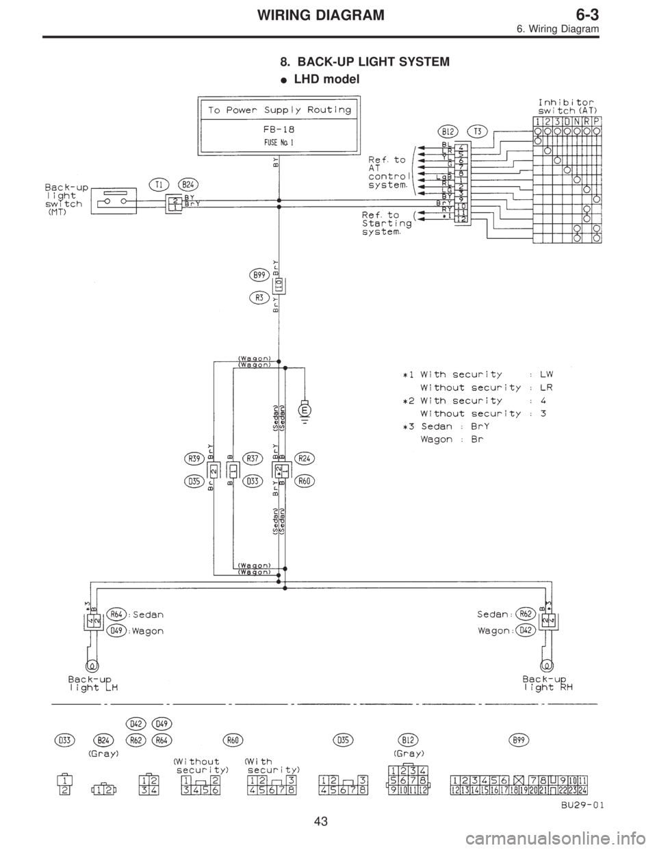
8. BACK-UP LIGHT SYSTEM
�LHD model
43
6-3WIRING DIAGRAM
6. Wiring Diagram
Page 3223 of 3342
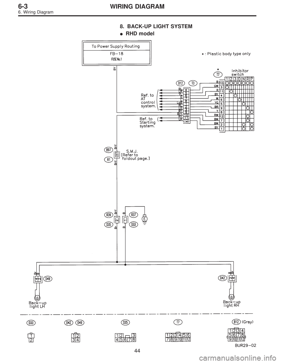
8. BACK-UP LIGHT SYSTEM
�RHD model
44
6-3WIRING DIAGRAM
6. Wiring Diagram
Page 3242 of 3342
14. FRONT FOG LIGHT SYSTEM
�Without DRL model
BU22-02
63
6-3WIRING DIAGRAM
6. Wiring Diagram