Page 3159 of 3342
B6M0180
1. CHECK CRUISE CONTROL MAIN SWITCH.
1) Remove cruise control main switch.
2) Measure resistance between cruise control main switch
terminals.
Terminals / Specified resistance:
No. 1—No. 6 / Approx. 50Ω
B6M0528A
B6M0531A
2. CHECK CIRCUIT BETWEEN CRUISE CONTROL
MODULE AND CRUISE CONTROL MAIN SWITCH
INDICATOR LIGHT.
1) Turn the ignition switch to ON.
2) Turn cruise control main switch to ON.
3) Measure voltage between cruise control main switch
connector and the body.
Connector & terminal / Specified voltage:
(i19) No. 1—Body / 10 V, or more
4) Turn the ignition switch and cruise control main switch
to OFF.
5) Remove the connector from the cruise control main
switch.
6) Measure resistance of ground circuit between the
cruise control main switch connector and body.
Connector & terminal / Specified resistance:
(i19) No. 6—Body / 10Ω, max.
13
6-2BODY ELECTRICAL SYSTEM
7. Diagnostics Chart for Power Line
Page 3162 of 3342

8. Diagnostics Chart with Trouble Code
A: TROUBLE CODE
Trouble code Item Contents of diagnosis Page
10 OK Normal 18
11 BRAKE/ST/CL or N�Input signals from brake switch“OFF”, stop light
switch“ON”(Brake pedal is in depressed condi-
tion.)
�Input signals from clutch switch“OFF”, or inhibi-
tor switch is in“N”position.
[Clutch pedal is depressed (MT), or select lever
is set to N position (AT).]20
12 NOT SET SP Out of cruise speed range 22
13 LOW SP LIM Low-speed control limiter 22
14 CANCEL SW Input signal from cancel switch 26
15 NO MEMORY No memorized cruise speed—
21 SP SENS NG Faulty vehicle speed sensor 2 22
22 COM SW NGFaulty SET/COAST switch or RESUME/ACCEL
switch26
23 RELAY NG Faulty safety relay included in cruise control module 29
24 CPU RAM NG Faulty CPU RAM included in cruise control module 29
31 MOTOR NG Faulty vacuum motor or motor drive system 30
32 AIR VAL NG Faulty air valve or valve drive system 30
33 REL VAL NG Faulty release valve or valve drive system 30
16
6-2BODY ELECTRICAL SYSTEM
8. Diagnostics Chart with Trouble Code
Page 3164 of 3342
BR
5 Inhibitor switch (AT) N
6——
7——
8——
9——
10—�")
LED No. Signal name Display
1 SET/COAST switch SE
2 RESUME/ACCEL switch RE
3 Stop light switch ST
4�Brake switch
�Clutch switch (MT)BR
5 Inhibitor switch (AT) N
6——
7——
8——
9——
10——
SE RE ST BR N
—————
1
2345
678910
1. CHECK THE SIGNAL USING A SELECT MONITOR.
1) Turn ignition switch to ON.
2) Turn cruise control main switch to ON.
3) Set select monitor in“FA 0”mode.
4) Check signals for proper operation.
(1) When pushing the SET switch:
LED No. 1 goes out—lights.
(2) When pushing the RESUME switch:
LED No. 2 goes out—lights.
B6M0533
B6M0527
2. CHECK THE CRUISE CONTROL COMMAND
SWITCH.
1) Disconnect connector from command switch.
2) Measure voltage between connector (S1) and body.
Connector & terminal / Specified voltage:
(S1) No. 1—Body / 10 V, or more
3) Check for harness short circuit between command
switch and body.
Terminals / Specified resistance:
No. 2—Body / 1 MΩ, min.
No. 3—Body / 1 MΩ, min.
B6M0534
4) Measure resistance between each terminal of switch
side connector to check the switch operation.
Terminals:
No. 1—No. 2 (SET/COAST SWITCH)
No. 1—No. 3 (RESUME/ACCEL SWITCH)
Specified resistance:
10Ω, max. (ON)
1MΩ, min. (OFF)
18
6-2BODY ELECTRICAL SYSTEM
8. Diagnostics Chart with Trouble Code
Page 3165 of 3342
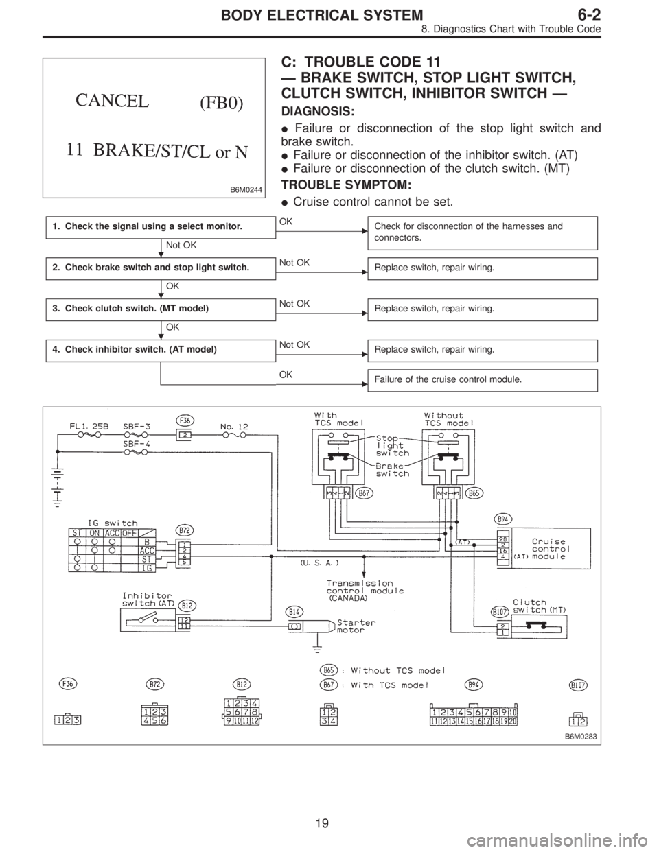
B6M0244
C: TROUBLE CODE 11
—BRAKE SWITCH, STOP LIGHT SWITCH,
CLUTCH SWITCH, INHIBITOR SWITCH—
DIAGNOSIS:
�Failure or disconnection of the stop light switch and
brake switch.
�Failure or disconnection of the inhibitor switch. (AT)
�Failure or disconnection of the clutch switch. (MT)
TROUBLE SYMPTOM:
�Cruise control cannot be set.
1. Check the signal using a select monitor.
Not OK
�OK
Check for disconnection of the harnesses and
connectors.
2. Check brake switch and stop light switch.
OK
�Not OK
Replace switch, repair wiring.
3. Check clutch switch. (MT model)
OK
�Not OK
Replace switch, repair wiring.
4. Check inhibitor switch. (AT model)�Not OK
Replace switch, repair wiring.
�OK
Failure of the cruise control module.
B6M0283
�
�
�
19
6-2BODY ELECTRICAL SYSTEM
8. Diagnostics Chart with Trouble Code
Page 3166 of 3342
BR
5 Inhibitor switch (AT) N
6——
7——
8——
9——
10—�")
LED No. Signal name Display
1 SET/COAST switch SE
2 RESUME/ACCEL switch RE
3 Stop light switch ST
4�Brake switch
�Clutch switch (MT)BR
5 Inhibitor switch (AT) N
6——
7——
8——
9——
10——
SE RE ST BR N
—————
1
2345
678910
1. CHECK THE SIGNAL USING A SELECT MONITOR.
1) Turn ignition switch to ON.
2) Turn cruise control main switch to ON.
3) Apply parking brake securely.
4) Set select monitor in“FA 0”mode.
5) Release the clutch pedal. (MT model)
6) Depress the brake pedal and check signals for proper
operation.
Stop light switch: LED No. 3 goes out—lights.
Brake switch : LED No. 4 goes out—lights.
7) Release the brake pedal.
8) Depress the clutch pedal and check signal for proper
operation. (MT model)
Clutch switch: LED No. 4 goes out—lights.
9) Set the selector lever from D to N position and check
signal for proper operation. (AT model)
Inhibitor switch: LED No. 5 goes out—lights.
G6M0183
2. CHECK BRAKE SWITCH AND STOP LIGHT
SWITCH.
1) Remove connector of stop and brake switch.
2) Check circuit between each terminal.
Pedal operationBrake switch between
No. 1—No. 4Stop light switch between
No. 2—No. 3
Depressing the
brake pedal.1MΩ,ormore 1Ω, or less
Without
depressing the
brake pedal.1Ω, or less 1 MΩ,ormore
G6M0184
3. CHECK CLUTCH SWITCH. (MT MODEL)
1) Disconnect connector from clutch switch.
2) Check continuity of the clutch switch.
Terminals / Specified resistance:
No. 1—No. 2 / 10Ω, max. (Without pedal
depressing.)
/1MΩ, min. (Pedal depressing.)
20
6-2BODY ELECTRICAL SYSTEM
8. Diagnostics Chart with Trouble Code
Page 3180 of 3342
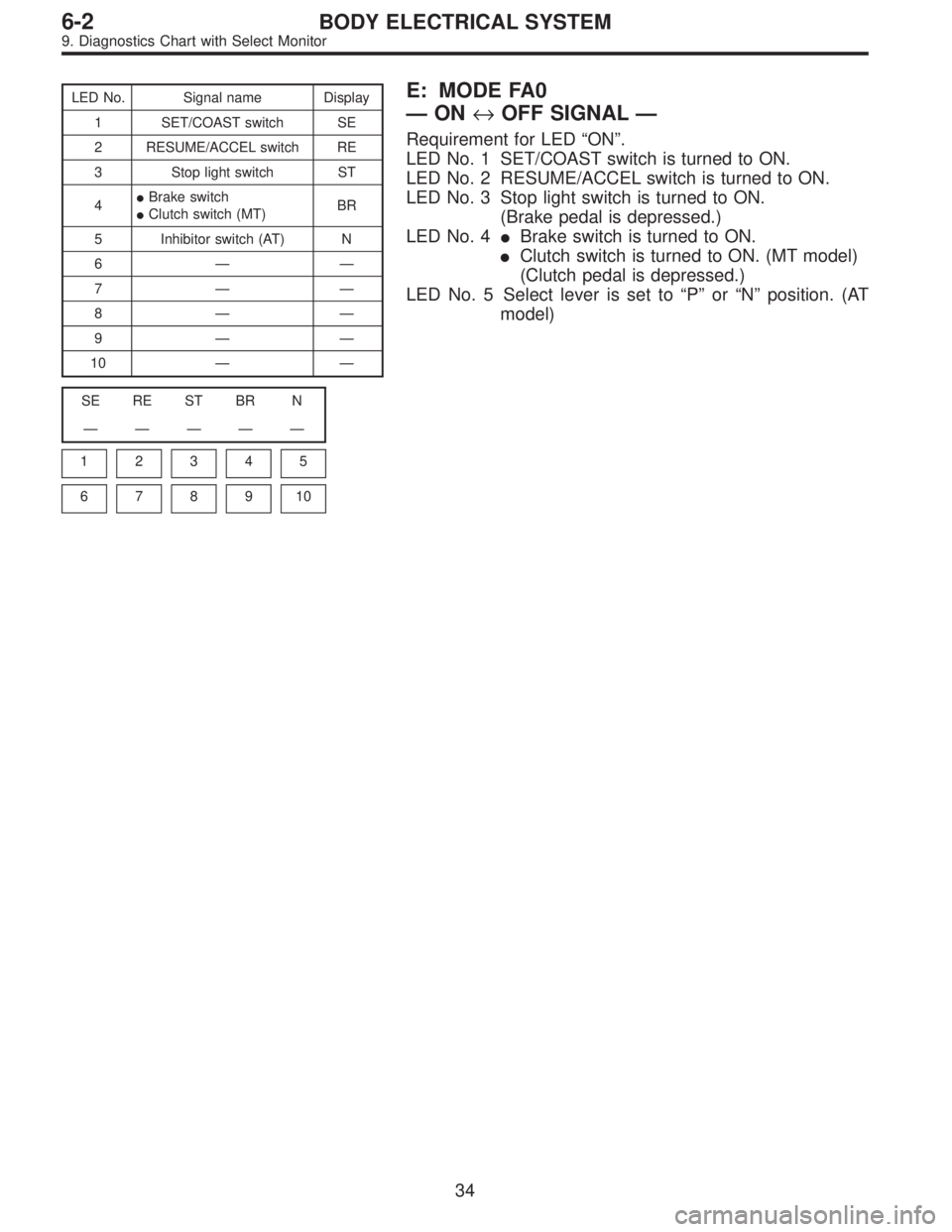
LED No. Signal name Display
1 SET/COAST switch SE
2 RESUME/ACCEL switch RE
3 Stop light switch ST
4�Brake switch
�Clutch switch (MT)BR
5 Inhibitor switch (AT) N
6——
7——
8——
9——
10——
SE RE ST BR N
—————
1
2345
678910
E: MODE FA0
—ON↔OFF SIGNAL—
Requirement for LED“ON”.
LED No. 1 SET/COAST switch is turned to ON.
LED No. 2 RESUME/ACCEL switch is turned to ON.
LED No. 3 Stop light switch is turned to ON.
(Brake pedal is depressed.)
LED No. 4�Brake switch is turned to ON.
�Clutch switch is turned to ON. (MT model)
(Clutch pedal is depressed.)
LED No. 5 Select lever is set to“P”or“N”position. (AT
model)
34
6-2BODY ELECTRICAL SYSTEM
9. Diagnostics Chart with Select Monitor
Page 3183 of 3342
 The sketch of each connector in the wiring diagram
usually shows the“A”side of the connector. The relation-
ship between the wire color, terminal number and connec-
tor is described in")
G6M0200
4) The sketch of each connector in the wiring diagram
usually shows the“A”side of the connector. The relation-
ship between the wire color, terminal number and connec-
tor is described in figure.
NOTE:
A wire which runs in one direction from a connector termi-
nal sometimes may have a different color from that which
runs in the other direction from that terminal.
G6M0216
5) In wiring diagram, connectors which have no terminal
number refer to one-pole types. Sketches of these connec-
tors are omitted intentionally.
G6M0201
6) The following color codes are used to indicate the col-
ors of the wires used.
Color code Color
L Blue
B Black
Y Yellow
G Green
RRed
W White
Br Brown
Lg Light green
Gr Gray
P Pink
Or Orange
Lb Light Blue
V Violet
SA Sealed (Inner)
SB Sealed (Outer)
G6M0202
7) The wire color code, which consists of two letters (or
three letters including Br or Lg), indicates the standard
color (base color of the wire covering) by its first letter and
the stripe marking by its second letter.
4
6-3WIRING DIAGRAM
1. General Description
Page 3186 of 3342
G6M0205
11) Each connector number shown in the wiring diagram
corresponds to that in the wiring harness. The location of
each connector in the actual vehicle is determined by read-
ing the first character of the connector (for example, a“F”
for F8,“i”for i16, etc.) and the type of wiring harness.
The first character of each connector number refers to the
area or system of the vehicle, as indicated in table below.
Symbol Wiring harness and Cord
F Front wiring harness
B Bulkhead wiring harness
E Engine wiring harness
T Transmission cord
D Door cord LH & RH, Rear gate cord
I Instrument panel wiring harness
RRear wiring harness, Rear defogger cord
Room light cord,
Fuel tank cord,
Sunroof cord,
Trunk lid cord
P Floor wiring harness
7
6-3WIRING DIAGRAM
1. General Description
 Remove cruise control main switch.
2) Measure resistance between cruise control main switch
terminals.
Terminals / Specified resistance:
No. 1—No. 6 /")
 Each connector number shown in the wiring diagram
corresponds to that in the wiring harness. The location of
each connector in the actual vehicle is determined by read-
ing the first chara")