Page 1601 of 3342
B5M0467A
11. REAR DOOR CATCHER
1) Open the rear door.
2) Using TORX
®BIT (Tamper resistant type), remove rear
door catcher.
3) Installation is in the reverse order of removal.
Tightening torque:
37±10 N⋅m (3.8±1.0 kg-m, 27.5±7.2 ft-lb)
B: ADJUSTMENT
1. DOOR ASSY
1) Using ST, loosen bolts securing upper and lower hinges
to body, and adjust fore-and-aft and vertical alignment of
door.
ST 925610000 DOOR HINGE WRENCH
B5M0071A
2) Loosen mounting screws approximately one rotation.
Adjust striker�
1position by lightly tapping with hammer. (To
adjust, utilize the shape of striker nut plate�
2support.)
CAUTION:
�Use cloth to prevent damaging body or other parts.
�Do not directly tap striker plastic portion.
�Do not apply impact on spot-welded striker nut
plate.
Hinge tightening torque (body side):
29±5 N⋅m (3.0±0.5 kg-m, 21.7±3.6 ft-lb)
Striker tightening torque:
14±4 N⋅m (1.4±0.4 kg-m, 10.1±2.9 ft-lb)
19
5-2SERVICE PROCEDURE
2. Door
Page 1604 of 3342
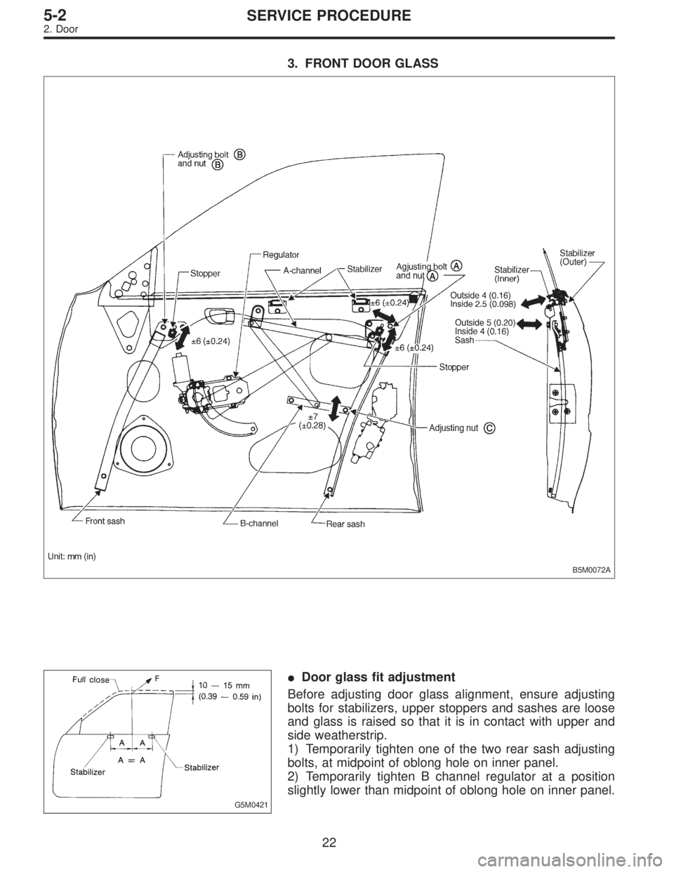
3. FRONT DOOR GLASS
B5M0072A
G5M0421
�Door glass fit adjustment
Before adjusting door glass alignment, ensure adjusting
bolts for stabilizers, upper stoppers and sashes are loose
and glass is raised so that it is in contact with upper and
side weatherstrip.
1) Temporarily tighten one of the two rear sash adjusting
bolts, at midpoint of oblong hole on inner panel.
2) Temporarily tighten B channel regulator at a position
slightly lower than midpoint of oblong hole on inner panel.
22
5-2SERVICE PROCEDURE
2. Door
Page 1608 of 3342
4. REAR DOOR GLASS
Alignment of rear door glass is basically the same as for
the front door glass. Due to slight difference in adjustment
dimensions for fore-aft, up-down, and in-out alignments,
key points for rear door adjustment are described below.
B5M0078A
B5M0074A
�Fore-aft adjustment
1) Door glass alignment must be adjusted so that glass-
to-center pillar fit is equal at all points. Always use dimen-
sions (indicated in figure) as a guide during adjustment.
NOTE:
If dimensions are smaller than those indicated, glass will be
caught in weatherstrip and may not raise to the fully closed
position.
2) After making fore-aft adjustment, raise and lower glass
to ensure it is free from any binding.
26
5-2SERVICE PROCEDURE
2. Door
Page 1610 of 3342

3. Rear Gate
A: REMOVAL AND INSTALLATION
CAUTION:
�Be careful not to scratch coated surfaces of vehicle
body and window glass during removal. Place a cloth
over the affected area.
�Be careful not to damage trim panels.
�Use an assistant when handling heavy parts.
�Be careful not to damage or lose small parts.
B5M0080
1. REAR GATE ASSEMBLY
1) Remove clips from trim panel and detach trim panel.
CAUTION:
Be careful not to damage clips or their holes.
2) Disconnect connectors and terminal.
3) Disconnect rear washer hose from wiper motor.
4) Remove high-mount stop light.
5) If disconnected harness is re-used, tie connector with a
string and place on the upper side of rear gate for ready
use.
CAUTION:
Do not forcefully pull cords, lead wires, etc. since dam-
age may result; carefully extract them in a wavy motion
while holding connectors.
6) Remove both rubber ducts and then extract washer
hose and harness connector.
B5M0081
7) Gas stay
(1) Completely open rear gate.
(2) Remove bolts which hold gas stay to rear gate.
CAUTION:
�Be careful because rear gate drops while removing
bolts. Have an assistant support it while removing
bolts.
�Be sure to place a folded cloth between rear gate
and body to prevent scratches.
B5M0082
8) Remove the bolts which hold rear gate to hinge and
then detach rear gate.
28
5-2SERVICE PROCEDURE
3. Rear Gate
Page 1611 of 3342
 General precautions in handling rear gate gas stay.
CAUTION:
�Do not attempt to disassemble gas stay because its
cylinder is filled with gas.
�Before discarding gas stay, place it at a slig")
G5M0551
9) General precautions in handling rear gate gas stay.
CAUTION:
�Do not attempt to disassemble gas stay because its
cylinder is filled with gas.
�Before discarding gas stay, place it at a slight angle
with the cylinder body side facing up and drilla2to3
mm (0.08 to 0.12 in) dia. hole to completely discharge
the content. (Gas is odorless, colorless and harmless;
however, metal powder may come out of the hole.)
G5M0491
�It is good practice to place a vinyl sack over it before
drilling the hole because oil may spurt out. Be careful
to prevent vinyl cover from becoming entangled on the
drill.
�Be careful not to scratch the exposed section of
piston rod or allow oil or paint to come in contact with
it.
�Do not attempt to rotate the extended piston rod.
10) Installation is in the reverse order of removal.
CAUTION:
�Be sure to add sealer to hinge.
�When installing rear gate, be careful not to damage
coating on body and rear gate.
G5M0404
2. LATCH
1) Remove trim panel.
2) Disengage rod from holder (= key cylinder).
3) Remove bolts from auto-door lock actuator.
4) Remove bolts from latch, and detach latch.
5) Disconnect rear gate switch connector.
6) Disconnect auto-door lock actuator connector.
7) Detach latch.
8) Installation is in the reverse order of removal.
B5M0083
3. OUTER HANDLE
1) Remove trim panel.
2) Disconnect rod from outer handle.
3) Remove two nuts used to hold outer handle to the
inside of rear gate, and detach outer handle.
CAUTION:
Be careful not to damage packing when removing
outer handle.
4) Installation is in the reverse order of removal.
29
5-2SERVICE PROCEDURE
3. Rear Gate
Page 1617 of 3342
 Installation of glass
(1) Hold glass with rubber suction cups.
(2) Mount glass on body with matching pin aligned.
(3) Stick them fast by pressing all sides lightly.
G5M0496
10) Installation")
G5M0409
9) Installation of glass
(1) Hold glass with rubber suction cups.
(2) Mount glass on body with matching pin aligned.
(3) Stick them fast by pressing all sides lightly.
G5M0496
10) Installation of molding
(1) Remove adhesive overflowing from outside of
glass until it becomes level with outer height of glass.
Then, add adhesive to portions that need it, and clean
with alcohol or white gasoline.
(2) Install front side molding.
CAUTION:
Do not open and close door after moldings have been
installed. When opening and closing door for unavoid-
able reason, lower door glass and gently move door.
11) Water leakage test
Test for water leakage about one hour after installation.
CAUTION:
�Move vehicle very gently.
�Do not squirt strong hose stream on vehicle.
12) Spontaneous drying
After completing all operations, leave vehicle alone for 24
hours.
CAUTION:
When delivering vehicle to user, tell him that vehicle
should not be subjected to heavy shocks for at least
three days.
13) Install cowl panel and wiper arm.
6. Rear Window Glass
A: REMOVAL
1. 4 DOOR MODEL
1) Disconnect connector from rear defogger terminal.
2) Remove glass in the same manner as in windshield.
35
5-2SERVICE PROCEDURE
5. Windshield - 6. Rear Window Glass
Page 1618 of 3342
 Installation of glass
(1) Hold glass with rubber suction cups.
(2) Mount glass on body with matching pin aligned.
(3) Stick them fast by pressing all sides lightly.
G5M0496
10) Installation")
G5M0409
9) Installation of glass
(1) Hold glass with rubber suction cups.
(2) Mount glass on body with matching pin aligned.
(3) Stick them fast by pressing all sides lightly.
G5M0496
10) Installation of molding
(1) Remove adhesive overflowing from outside of
glass until it becomes level with outer height of glass.
Then, add adhesive to portions that need it, and clean
with alcohol or white gasoline.
(2) Install front side molding.
CAUTION:
Do not open and close door after moldings have been
installed. When opening and closing door for unavoid-
able reason, lower door glass and gently move door.
11) Water leakage test
Test for water leakage about one hour after installation.
CAUTION:
�Move vehicle very gently.
�Do not squirt strong hose stream on vehicle.
12) Spontaneous drying
After completing all operations, leave vehicle alone for 24
hours.
CAUTION:
When delivering vehicle to user, tell him that vehicle
should not be subjected to heavy shocks for at least
three days.
13) Install cowl panel and wiper arm.
6. Rear Window Glass
A: REMOVAL
1. 4 DOOR MODEL
1) Disconnect connector from rear defogger terminal.
2) Remove glass in the same manner as in windshield.
35
5-2SERVICE PROCEDURE
5. Windshield - 6. Rear Window Glass
Page 1620 of 3342
2. WAGON MODEL
B5M0090A
1) Install rear gate trim.
2) Install glass in the same manner as in windshield.
3) About one hour after installation, test for water leakage.
Leave vehicle for 24 hours before using it.
4) Connect rear defogger connections.
5) Install high-mount stop light and rear wiper.
37
5-2SERVICE PROCEDURE
6. Rear Window Glass
 Open the rear door.
2) Using TORX
®BIT (Tamper resistant type), remove rear
door catcher.
3) Installation is in the reverse order of removal.
Tightening torque:
37±")

 Install rear gate trim.
2) Install glass in the same manner as in windshield.
3) About one hour after installation, test for water leakage.
Leave vehicle for 24 hours before")