Page 1736 of 3342
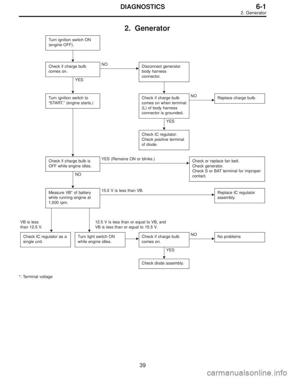
2. Generator
Turn ignition switch ON
(engine OFF).
Check if charge bulb
comes on.
YES
�NO
Disconnect generator
body harness
connector.
Turn ignition switch to
“START.”(engine starts.)Check if charge bulb
comes on when terminal
(L) of body harness
connector is grounded.
YES
�NO
Replace charge bulb.
Check IC regulator.
Check positive terminal
of diode.
Check if charge bulb is
OFF while engine idles.
NO
�YES (Remains ON or blinks.)
Check or replace fan belt.
Check generator.
Check S or BAT terminal for improper
contact.
Measure VB* of battery
while running engine at
1,500 rpm.�15.5 V is less than VB.
Replace IC regulator
assembly.
VB is less
than 12.5 V.12.5 V is less than or equal to VB, and
VB is less than or equal to 15.5 V.
Check IC regulator as a
single unit.
Turn light switch ON
while engine idles.�Check if charge bulb
comes on.
YES
�NO
No problems
Check diode assembly.
*: Terminal voltage
�
��
�
�
�
��
�
39
6-1DIAGNOSTICS
2. Generator
Page 1737 of 3342
, 100 minutes (AT)
Cold cranking ampere 430 amperes (MT), 490 amperes (AT)
Fuse10 A, 15 A, 20 A
Combination
meterSpeedometer")
1. Body Electrical
A: SPECIFICATIONS
BatteryReserve capacity 82 minutes (MT), 100 minutes (AT)
Cold cranking ampere 430 amperes (MT), 490 amperes (AT)
Fuse10 A, 15 A, 20 A
Combination
meterSpeedometer Electric pulse type
Tachometer Electric impulse type
Water temperature gauge Thermistor cross coil type
Fuel gauge Resistance cross coil type
Charge indicator light 12 V—1.4 W
Brake fluid level warning/parking brake indicator light 12 V—1.4 W
AT oil temperature warning light (AWD only) 12 V—1.4 W
ABS warning light 12 V—1.4 W
CHECK ENGINE warning light
(Malfunction indicator lamp)12 V—1.4 W
Oil pressure warning light 12 V—1.4 W
AIRBAG system warning light 12 V—1.4 W
Low fuel warning light 12 V—3W
FWD indicator light 12 V—1.4 W
TCS warning light 12 V—1.4 W
TCS indicator light 12 V—1.4 W
Turn signal indicator light 12 V—1.4 W (2 pieces)
Seat belt warning light 12 V—1.4 W
Door open warning light 12 V—1.4 W (5 pieces)
Headlight beam indicator light 12 V—1.4 W
Meter illumination light12 V—3 W (2 pieces)
12 V—3.4 W (4 pieces)
Headlight 12 V—60/55 W (Halogen)
Front clearance light 12 V—5W
Turn signal lightFront 12 V—21 W
Rear 12 V—21 W
Tail/Stop light 12 V—5/21 W
Back-up light 12 V—21 W
High-mount stop light12 V—18 W (SEDAN), 12 V—13 W
(WAGON)
License plate light 12 V—5W
Room light 12 V—8W
Trunk room light (SEDAN) 12 V—5W
Luggage room light (WAGON) 12 V—5W
Spot light 12 V—8 W (2 pieces)
Glove box light 12 V—3.4 W
Ash tray illumination light 12 V—1.7 W
Selector lever illumination light (AT model) 12 V—1.7 W
2
6-2SPECIFICATIONS
1. Body Electrical
Page 1738 of 3342
Front wiper
motorInput 12 V—54 W or less
Rear wiper motor Input 12 V—42 W or less
Front washer
motorPump type Centrifugal
Input 12 V—36 W or less
Rear washer
motorPump type Centrifugal
Input 12 V—36 W or less
Horn12 V—350 Hz
Cigarette lighter Input 12 V—120 W
Rear window
defoggerInput 12 V—160 W
Indicator light 12 V—50 mA
3
6-2SPECIFICATIONS
1. Body Electrical
Page 1745 of 3342

1) Remove instrument panel lower cover.
2) Remove lower column cover.
3) Unfasten holddown clip which secures harness, and
disconnect connector of ign")
B6M0048
B: INSPECTION
1. IGNITION SWITCH (ON-CAR)
1) Remove instrument panel lower cover.
2) Remove lower column cover.
3) Unfasten holddown clip which secures harness, and
disconnect connector of ignition switch from body harness.
4) Turn ignition key to each position and check continuity
between terminals of ignition switch connector.
Terminal
Positiona-1 a-2 a-5 a-4
LOCK
ACC��
ON���
START���
B6M0824A
4. Headlight
A: ADJUSTMENT
1. HEADLIGHT AIMING
1) Adjust the headlight aiming by turning the adjusting
screws.
CAUTION:
Before checking the headlight aiming, be sure of the
following:
�Turn off the light before adjusting headlight aiming.
If the light is necessary to check aiming, do not turn on
for more than two minutes.
�The area around the headlight has not sustained any
accident, damage or other type of deformation.
�Vehicle is parked on level ground.
�The inflation pressure of tires is correct.
�Vehicle’s gas tank is fully charged.
�Bounce the vehicle several times to normalize the
suspension.
�Make certain that someone is seated in the driver’s
seat.
NOTE:
Adjust vertical aim first, then horizontal aim.
8
6-2SERVICE PROCEDURE
3. Ignition Switch - 4. Headlight
Page 1746 of 3342

1) Remove instrument panel lower cover.
2) Remove lower column cover.
3) Unfasten holddown clip which secures harness, and
disconnect connector of ign")
B6M0048
B: INSPECTION
1. IGNITION SWITCH (ON-CAR)
1) Remove instrument panel lower cover.
2) Remove lower column cover.
3) Unfasten holddown clip which secures harness, and
disconnect connector of ignition switch from body harness.
4) Turn ignition key to each position and check continuity
between terminals of ignition switch connector.
Terminal
Positiona-1 a-2 a-5 a-4
LOCK
ACC��
ON���
START���
B6M0824A
4. Headlight
A: ADJUSTMENT
1. HEADLIGHT AIMING
1) Adjust the headlight aiming by turning the adjusting
screws.
CAUTION:
Before checking the headlight aiming, be sure of the
following:
�Turn off the light before adjusting headlight aiming.
If the light is necessary to check aiming, do not turn on
for more than two minutes.
�The area around the headlight has not sustained any
accident, damage or other type of deformation.
�Vehicle is parked on level ground.
�The inflation pressure of tires is correct.
�Vehicle’s gas tank is fully charged.
�Bounce the vehicle several times to normalize the
suspension.
�Make certain that someone is seated in the driver’s
seat.
NOTE:
Adjust vertical aim first, then horizontal aim.
8
6-2SERVICE PROCEDURE
3. Ignition Switch - 4. Headlight
Page 1747 of 3342
B6M0336A
2) Look at the beam angle gauge (vertical movement).
The bubble on the gauge should not deviate from the cen-
ter of the gauge.
B6M0825A
3) Look at the beam angle gauge (horizontal movement).
The indicator should not deviate from the center of the
gauge by more than two segments on either side of the
gauge.
B: REMOVAL AND INSTALLATION
1. HEADLIGHT BULB
1) Disconnect the connector from inside of the engine
compartment.
2) Remove rubber cap.
3) Remove the light bulb retaining spring to remove the
bulb.
4) Replace the bulb with a new one and hook the spring.
5) Attach the rubber cap and connect the connector.
M6A0139
CAUTION:
�Since the tungsten halogen bulb operates at high
temperature, dirt and oil on the bulb surface decreases
the bulb’s useful life. When replacing the bulb, hold the
flange portion and do not touch the glass portion.
9
6-2SERVICE PROCEDURE
4. Headlight
Page 1748 of 3342
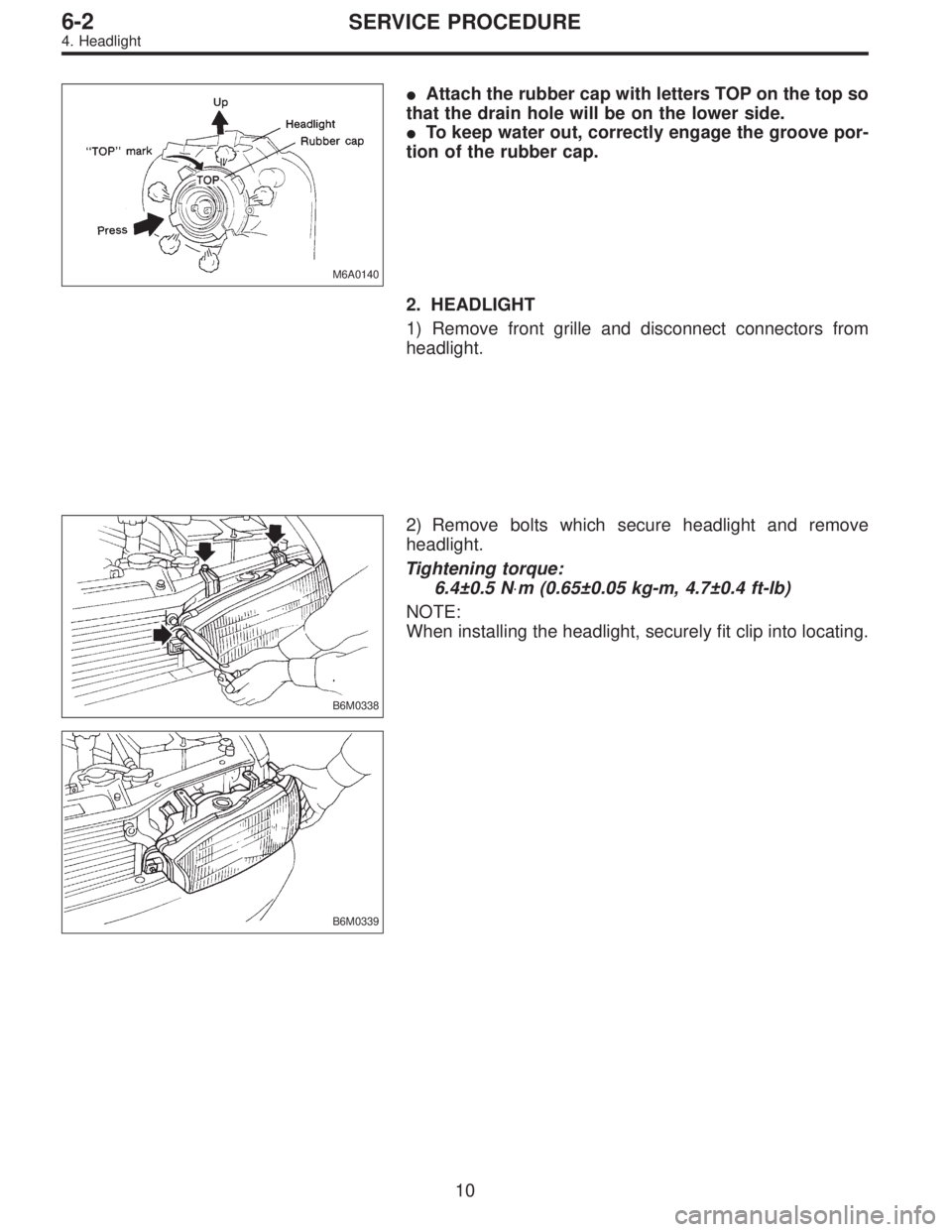
M6A0140
�Attach the rubber cap with letters TOP on the top so
that the drain hole will be on the lower side.
�To keep water out, correctly engage the groove por-
tion of the rubber cap.
2. HEADLIGHT
1) Remove front grille and disconnect connectors from
headlight.
B6M0338
2) Remove bolts which secure headlight and remove
headlight.
Tightening torque:
6.4±0.5 N⋅m (0.65±0.05 kg-m, 4.7±0.4 ft-lb)
NOTE:
When installing the headlight, securely fit clip into locating.
B6M0339
10
6-2SERVICE PROCEDURE
4. Headlight
Page 1749 of 3342
![SUBARU LEGACY 1997 Service Repair Manual B6M0236
3. COMBINATION SWITCH (WITHOUT AIRBAG
MODEL)
Refer to 5-5 [W7A0] as for removal of combination
switch on airbag equipped model.
1) Remove steering wheel. <Ref. to 4-3 [W2A0].>
2) Remove screws](/manual-img/17/57434/w960_57434-1748.png "SUBARU LEGACY 1997 Service Repair Manual B6M0236
3. COMBINATION SWITCH (WITHOUT AIRBAG
MODEL)
Refer to 5-5 [W7A0] as for removal of combination
switch on airbag equipped model.
1) Remove steering wheel. <Ref. to 4-3 [W2A0].>
2) Remove screws")
B6M0236
3. COMBINATION SWITCH (WITHOUT AIRBAG
MODEL)
Refer to 5-5 [W7A0] as for removal of combination
switch on airbag equipped model.
1) Remove steering wheel.
2) Remove screws which secure upper column cover to
lower column cover.
3) Remove screws which secure knee protector and
remove knee protector.
CAUTION:
When installing knee protector, ensure that harness is
not caught by adjacent parts.
4) Disconnect connector from body harness and undo
holddown band.
G6M0107
5) Remove screws which secure switch and remove
switch.
CAUTION:
During installation (with key interlock)
�When routing combination switch harness around
steering system, do not place it over key interlock
release knob.
�After installing lower column cover, ensure that key
interlock release knob is accessible.
B6M0237
C: DISASSEMBLY AND ASSEMBLY
1. COMBINATION SWITCH
1) Remove screws which secure slip ring to combination
switch, and remove slip ring.
G6M0109
2) Remove screws which secure lighting switch, wiper and
washer switch. Remove both switches.
Assembly is in the reverse order of disassembly.
11
6-2SERVICE PROCEDURE
4. Headlight

 Look at the beam angle gauge (vertical movement).
The bubble on the gauge should not deviate from the cen-
ter of the gauge.
B6M0825A
3) Look at the beam angle gauge (horizontal movement).")